

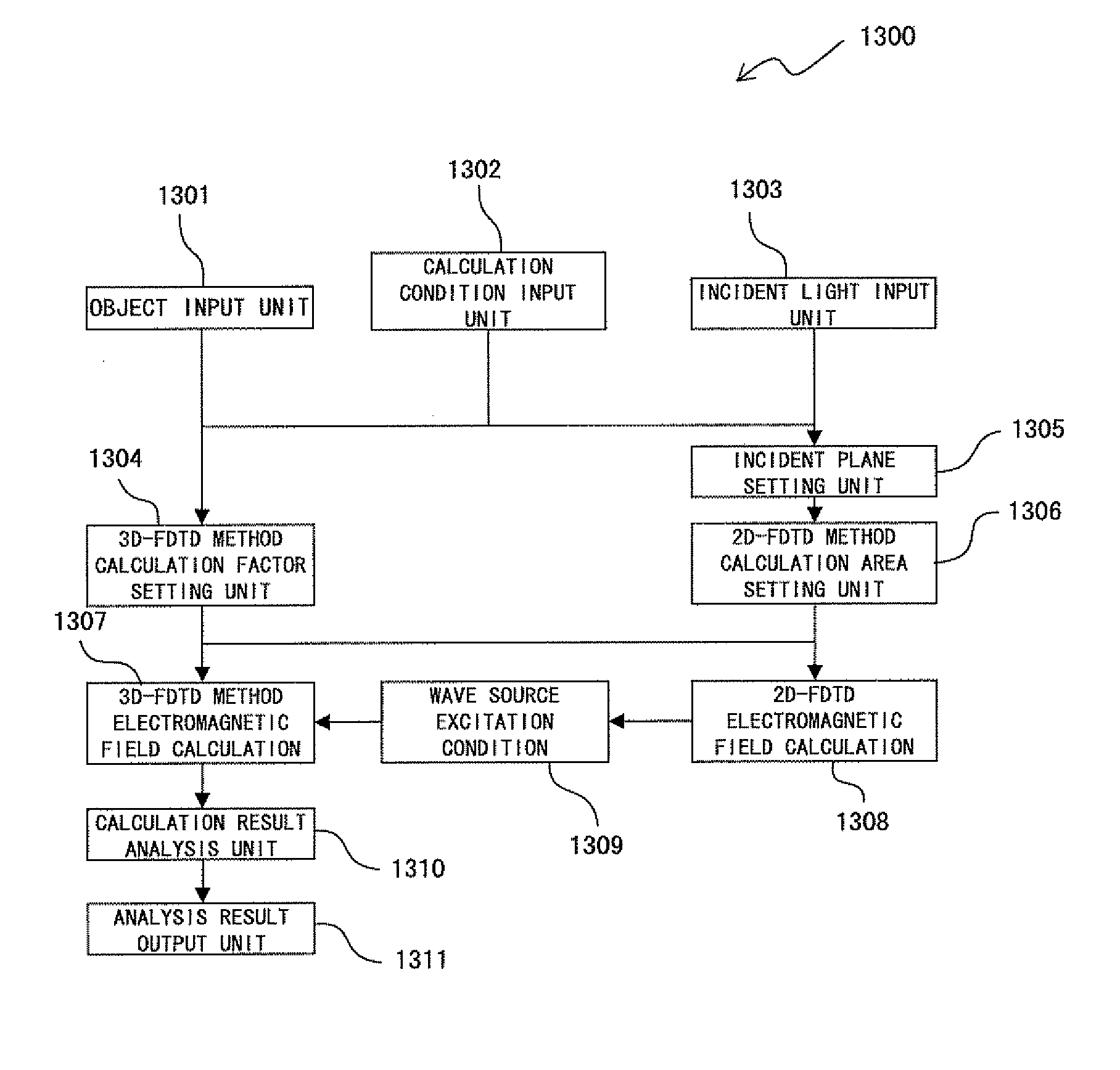
Electromagnetic field simulator and electromagnetic field simulating program product
a simulator and electromagnetic field technology, applied in the field of electromagnetic field simulator and electromagnetic field simulation program product, can solve the problems of inability to use a ray tracing technique, inability to analyze the light source such as a laser device and the like, and inability to set incident light as a plane wave with uniform intensity distribution
- Summary
- Abstract
- Description
- Claims
- Application Information
AI Technical Summary
Benefits of technology
Problems solved by technology
Method used
Image

Examples
Embodiment Construction
[0080]The embodiments of the present invention are explained below by referring to the attached drawings.
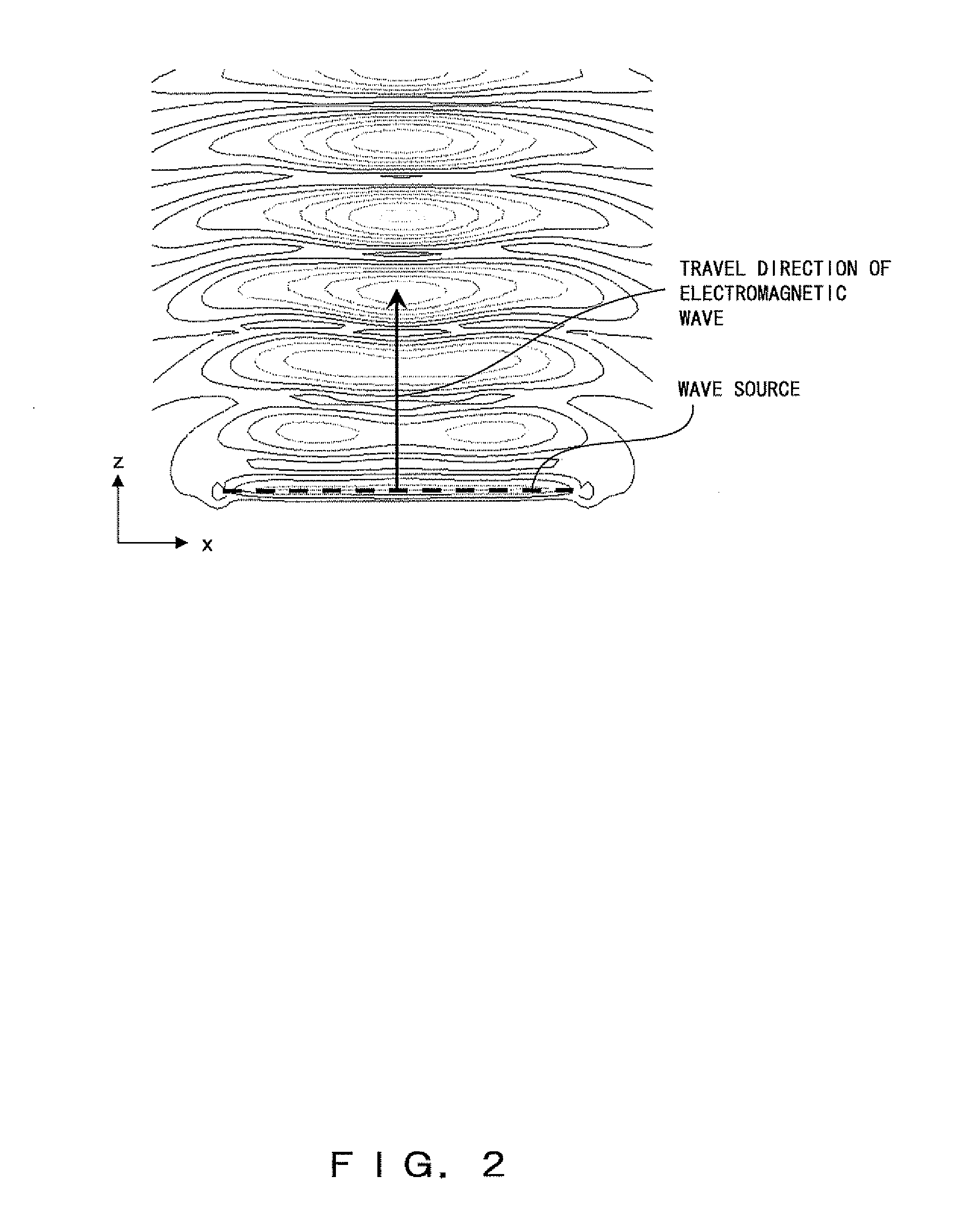
[0081]Non-uniform incident intensity occurs by the interference of an incident wave and a reflected wave when there is a substrate for reflecting an electromagnetic wave on an analysis target. This phenomenon occurs not only in calculation, but also when light is actually launched into the reflection plane. Therefore, an actual phenomenon is reproduced for the intensity distribution in the direction perpendicular to the substrate, and is not an incorrect result. However, with respect to the direction parallel to the substrate, uniform intensity is required if the beam diameter is sufficiently large, and there is not a small difference between an analysis and an actual phenomenon. This is caused by the excitation condition of a wave source.
[0082]The reason for not possibly and uniformly setting a direction parallel to the substrate is that the excitation condition of the electric ...
PUM
 Abstract
Description
Claims
Application Information