Antenna cable

Inactive Publication Date: 2008-04-03
CARDIOMEMS
View PDF24 Cites 66 Cited by
  • Summary
  • Abstract
  • Description
  • Claims
  • Application Information

AI Technical Summary

Benefits of technology

[0010] In some embodiments, the inner cables include an internal signal cable shield to prevent or reduce external interference. The inner cables and coaxial cable may be cased in an outer shielding to prevent or reduce external interference. Shields such as ferrite beads may be connected to at least some sub-component cables at or near the end of a cable to (1) reduce

Problems solved by technology

An abdominal aortic aneurysm (AAA) is a dilatation and weakening of the abdominal aorta that can lead to aortic rupture and sudden death.
However, a significant problem that has emerged with these stent-grafts for AAAs is acute and late leaks of blood into the aneurysm's sac.
This is an expensive, risky procedure that lacks appropriate sensitivity to detect small lea

Method used


Image

  • Antenna cable
  • Antenna cable
  • Antenna cable

Examples


Embodiment Construction

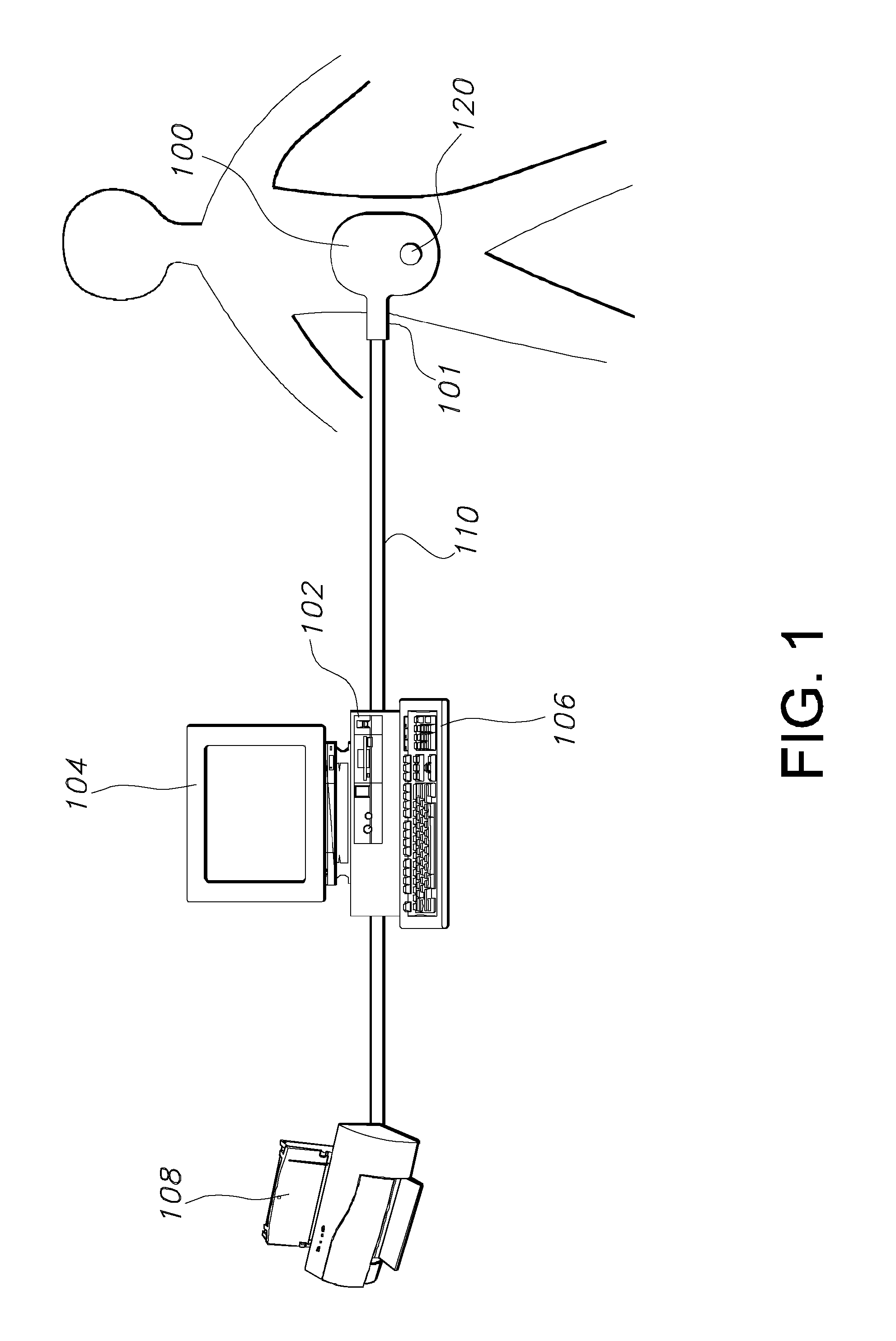
[0017] As described in the Related Applications, a cable assembly connects the antenna to a base unit in a system for communicating with a wireless sensor implanted within a body. FIG. 1 illustrates one embodiment of such a system. The system includes an antenna, such as coupling loop 100, a base unit 102, a display device 104 and an input device 106. Examples of input device 106 can include a keyboard, a mouse, or otherwise. The display device 104 may also include input device 106, such as a touch screen. The base unit 102 can include an RF amplifier, a receiver, and signal processing circuitry.

[0018] The display device 104 and the input device 106 are used in connection with the user interface for the system. In the embodiment illustrated in FIG. 1, the display device 104 and the input device 106 are connected to the base unit 102. In this embodiment, the base unit 102 also provides conventional computing functions. In other embodiments, the base unit 102 can be connected to a co...


PUM


Abstract

Embodiments of the present invention are directed to a cable assembly that is adapted to be connected to an antenna and a base unit. The cable assembly may be relatively flat with shielding and structures to reduce ground currents or other interference. Embodiments of the cable assembly include at least two coaxial cables for transmit and receive signals that are separated to reduce crosstalk or other interference. The cable may also include one or more inner cables, such as differential or switching pairs, between the two coaxial cables to provide cables for control, power, switching, or other functions. The inner cables may be positioned in parallel to each other and to each of the coaxial cables. In some embodiments, the inner cables include a first inner cable located at a first end of the inner cables and a second inner cable located at a second end of the inner cables. One coaxial cable may be positioned adjacent and parallel to the first inner cable, which the other coaxial cable may be positioned adjacent and parallel to the second inner cable.

Description

CROSS REFERENCE TO RELATED APPLICATIONS [0001] This application claims priority to U.S. Provisional Patent Application No. 60 / 824,924, titled “Antenna Cable,” filed Sep. 8, 2006, the entire contents of which is incorporated herein by reference. [0002] This application is related to U.S. patent application Ser. No. 11 / 668,601, titled “Cable Assembly for a Coupling Loop,” filed Jan. 1, 2007, which is a continuation of U.S. patent application Ser. No. 11 / 479,527, filed Jun. 30, 2006, which claims the benefit of U.S. Provisional Application No. 60 / 697,867, filed Jul. 8, 2005, and is a continuation-in-part of U.S. patent application Ser. No. 11 / 105,294, filed Apr. 13, 2005, which claims the benefit of U.S. Provisional Patent Application No. 60 / 623,959, filed Nov. 1, 2004; U.S. Provisional Application No. 60 / 697,878, filed Jul. 8, 2005 and U.S. Provisional Application No. 60 / 707,094, filed Aug. 10, 2005, the contents of each of which is incorporated herein by this reference (and which are...

Claims


Application Information

Patent Timeline
IPC IPC(8): H01B11/20
CPCH01B11/203H01B7/0861
Inventor MILLER, DONALD J.KROH, JASON
Owner CARDIOMEMS
Why Eureka
Try Eureka