Superconducting coil support structures

a superconducting coil and support structure technology, applied in the direction of windings, magnetic circuit rotating parts, magnetic circuit shapes/forms/constructions, etc., can solve the problems of reducing the power efficiency of the generator, carrying a substantial electric current, and mechanically massive and electrically complex structures

Inactive Publication Date: 2008-04-03
SIEMENS ENERGY INC +4
View PDF12 Cites 46 Cited by
  • Summary
  • Abstract
  • Description
  • Claims
  • Application Information

AI Technical Summary

Problems solved by technology

The generator is a mechanically massive and electrically complex structure, supplying output power up to 1,500 MVA at voltages up to 26 kilovolts.
Although the electrical resistance of copper is low compared to most other conductive materials, current flow through the copper conductors causes substantial rotor heating, diminishing the machine's power efficiency and requiring use of a cooling system to maintain the rotor at an appropriate operating temperature.
Since the superconducting materials exhibit substantially no electrical resistance when maintained at or below their critical temperature, these materials can carry a substantial electric current for a long duration with insignificant energy losses, including losses through the generation of heat.
Although the HTS rotor windings (coils) exhibit little resistance to current flow, they are sensitive to mechanical bending and tensile stresses that can cause premature degradation and winding failure (e.g., an open circuit).
Also, the HTS rotor winding may be subjected to over-speed forces during rotor balancing procedures at ambient temperature and occasional over-speed conditions at superconducting temperatures during power generation operation.
These over-speed and fault conditions substantially increase the centrifugal force loads on the rotor coil windings beyond the loads experienced during normal operating conditions.
The temperature excursions experienced during these operating cycles can lead to winding fatigue and must therefore be considered in the design of the HTS rotor windings.
Maintaining the structural integrity of the superconducting rotor windings against static and dynamic loads presents a formidable challenge to the development of a high temperature superconducting generator.

Method used


Image

  • Superconducting coil support structures
  • Superconducting coil support structures
  • Superconducting coil support structures

Examples


first embodiment

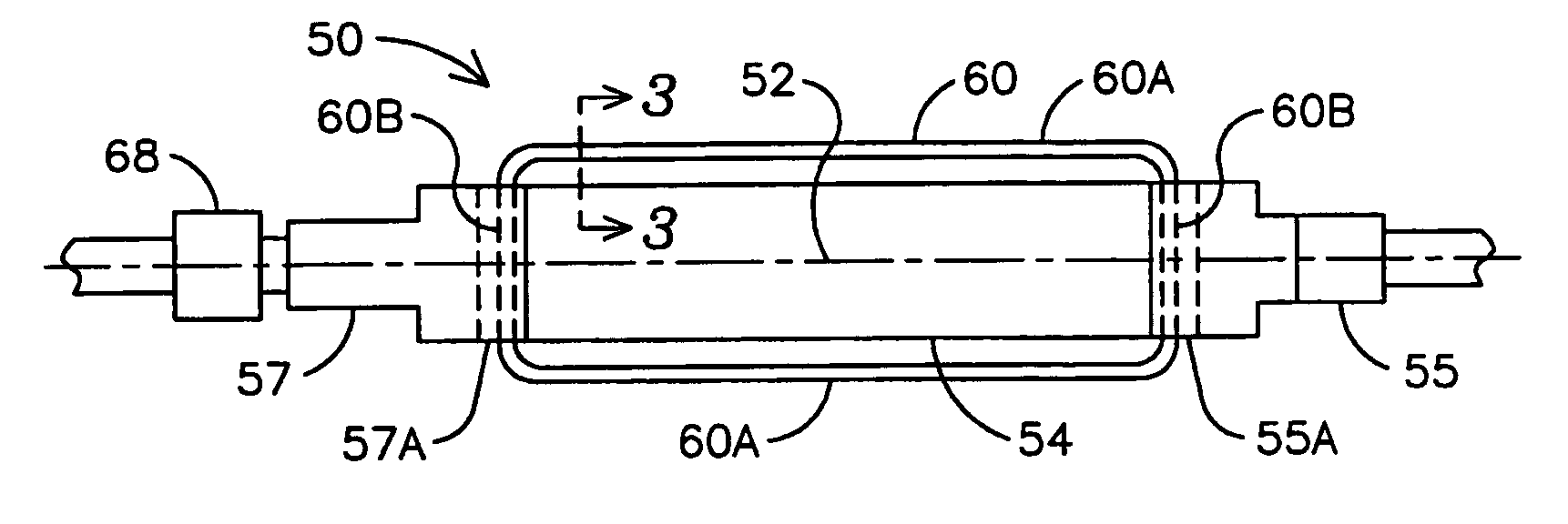
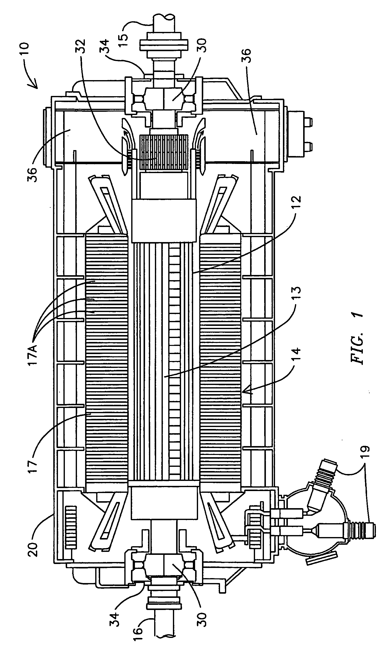
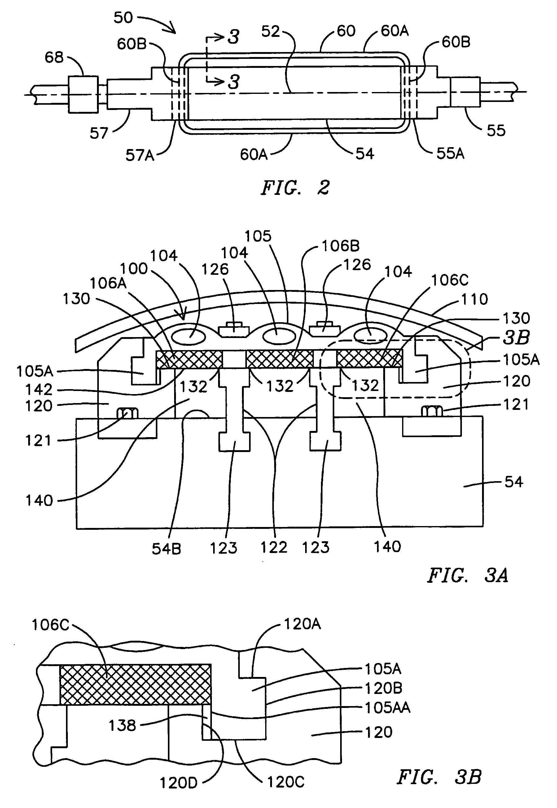
[0030]Existing non-superconducting dynamoelectric machines, such as the electric generator 10 of FIG. 1, may be retrofitted by replacing the non-superconducting rotor 12 with a superconducting rotor 50 illustrated in FIG. 2. The superconducting rotor 50 defines a longitudinally-extending axis 52 and comprises a generally cylindrically-shaped core 54 and coaxially aligned rotor end segments 55 and 57 each attached to an end surface of the core 54. A material of the core 54 exhibits a high magnetic permeability, e.g. a ferromagnetic material such as iron.

[0031]The superconducting rotor 50 further comprises a generally longitudinally-extending, racetrack-shaped superconducting coil or winding 60 comprising generally linear axial segments 60A connected by radial segments 60B, the latter extending through openings 55A and 57A between end surfaces of the core 54 and the respective end segments 55 and 57. In certain embodiments a vacuum shield, not shown in FIG. 2, surrounds the supercondu...

second embodiment

[0059]Another embodiment of a coil support structure of the present invention (illustrated in FIGS. 5A, 5B, 5C and 6) comprises a compression support structure 200 (see FIG. 5A) for supporting the three exemplary parallel superconducting blocks 106A, 106B and 106C against lateral loads (tangential loads with respect to the rotor core). The compression support structure 200 comprises overhang frames 202 (constructed from a material having a high thermal resistance such as fiber reinforced plastic). Base regions 202A of the overhang frames 202 extending beyond side surfaces of a conductor enclosure 212 are attached to the rotor core 54 by any suitable fastening technique. In another embodiment the base regions 202A are attached to a casing structure (not shown) surrounding the compression support structure 200 and attached to the core 54. The shape of the illustrated overhang frame 202 is merely exemplary as the shape can be optimized in response to expected normal and fault condition...

third embodiment

[0071]Another embodiment of a compression-type coil support 300 is illustrated in a perspective view of FIG. 7 and a sectional view of FIG. 8. Posts 308 are fixedly attached to the core 54 (not shown) (for example, threads formed in a lower region of the posts 308 threadably engage a mating threaded opening in the core 54). In conjunction with a plate 312 and a nut 314 (or another fastener as known by those skilled in the art) configured as illustrated, each post 308 exerts a compressive (radially inwardly directed) force on the superconducting block 106 and fiberglass reinforced plastic elements 315 disposed within wells 316 in sidewall surfaces of a conductor enclosure 318 to transfer the compressive force exerted by the plates 312 to the conductor enclosure 316, thereby compressively biasing the conductor block 106.


PUM


Abstract

Support structures (100) for attaching superconducting conductors (106) to a rotor (50) of an electrical machine (10). The support structures (100) are mechanically configured to transfer loads exerted on the superconducting conductors (106) during both normal and transient operation of the rotor (50). The mechanical configuration and material of the support structures (100) further present a thermal path that is longer than the physical distance between the superconducting conductors (106) and the rotor (50) thereby minimizing heat flow from the warm rotor (50) to the cold superconducting conductors (106).

Description

FIELD OF THE INVENTION[0001]This invention relates in general to mechanical support structures and more particularly to mechanical support structures for supporting a superconducting coil of a dynamoelectric machine.BACKGROUND OF THE INVENTION[0002]An electric generator transforms rotational energy into electrical energy according to generator action principles of a dynamoelectric machine. The turning torque supplied to a rotating rotor by a combustion or steam-driven turbine is converted to alternating current (AC) electricity, typically three-phase AC, in a stationary stator that surrounds the rotor. The generator is a mechanically massive and electrically complex structure, supplying output power up to 1,500 MVA at voltages up to 26 kilovolts. Electrical generators are the primary power producers in an electrical power system.[0003]As shown in FIG. 1, a conventional electric generator 10 comprises a substantially cylindrical rotor 12 supporting axial field windings or rotor windi...

Claims


Application Information

Patent Timeline
Patent Type & Authority Applications(United States)
IPC IPC(8): H02K9/00H02K1/22
CPCH02K3/527Y02E40/625H02K55/04Y02E40/60
Inventor ZHANG, JIPINGNELSON, ROBERT J.CLAYTON, PETER J.MCCOWN, WILLIAM R.
Owner SIEMENS ENERGY INC
Why Eureka
Try Eureka