Car power source apparatus

a technology for power sources and cars, applied in the direction of electric devices, battery/fuel cell control arrangements, instruments, etc., can solve the problems of shortening the life of batteries, affecting the operation of driving batteries, and affecting the electrical characteristics of batteries

Active Publication Date: 2008-04-03
SANYO ELECTRIC CO LTD
View PDF2 Cites 25 Cited by
  • Summary
  • Abstract
  • Description
  • Claims
  • Application Information

AI Technical Summary

Benefits of technology

[0011]The principle by which the car power source apparatus above determines open circuit for a plurality of voltage detection lines while measuring voltage at one voltage detection node is described based on FIG. 1. In this car power source apparatus, the output-side of the driving battery 1 is connected to the input-side of the voltage detection circuit 3 via two voltage detection lines 8. When neither of the two voltage detection lines 8 is open circuited, voltage at a voltage detection node 9 is input to the voltage detection circuit 3 via parallel-connected voltage drop resistors 10. In the car power source apparatus of the figure, the two voltage detection lines 8 are connected to a common input line 11 and connected to the input-side of the voltage detection circuit 3 via the common input line 11. Therefore, the voltage input to the voltage detection circuit 3 is the voltage from the voltage divider formed by the series addition of the voltage divider resistor 12 (R1) and the parallel-connected voltage drop resistors 10 (R3), and the input resistor 13 (R2). If the electrical resistance of each voltage detection line 8 voltage drop resistor 10 (R3) is the same, the resistance of the parallel-connected voltage detection lines 8 is one half of tha...

Problems solved by technology

This is because over-charging and over-discharging degrade battery electrical characteristics and shorten battery lifetime.
This is because the condition of the driving battery cannot be determined if driving battery voltage cannot be detected.
If a voltage detection line becomes open circuited, voltage detection node voltage is...

Method used


Image

  • Car power source apparatus
  • Car power source apparatus
  • Car power source apparatus

Examples


Embodiment Construction

)

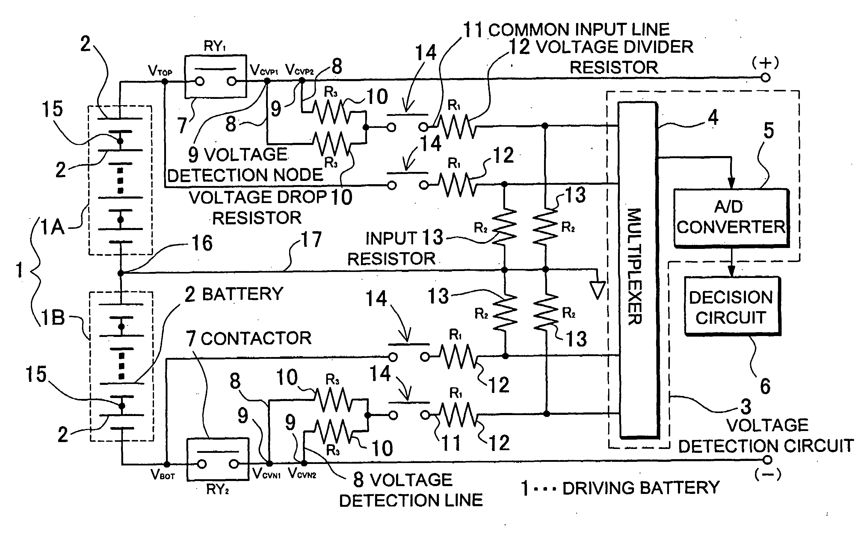
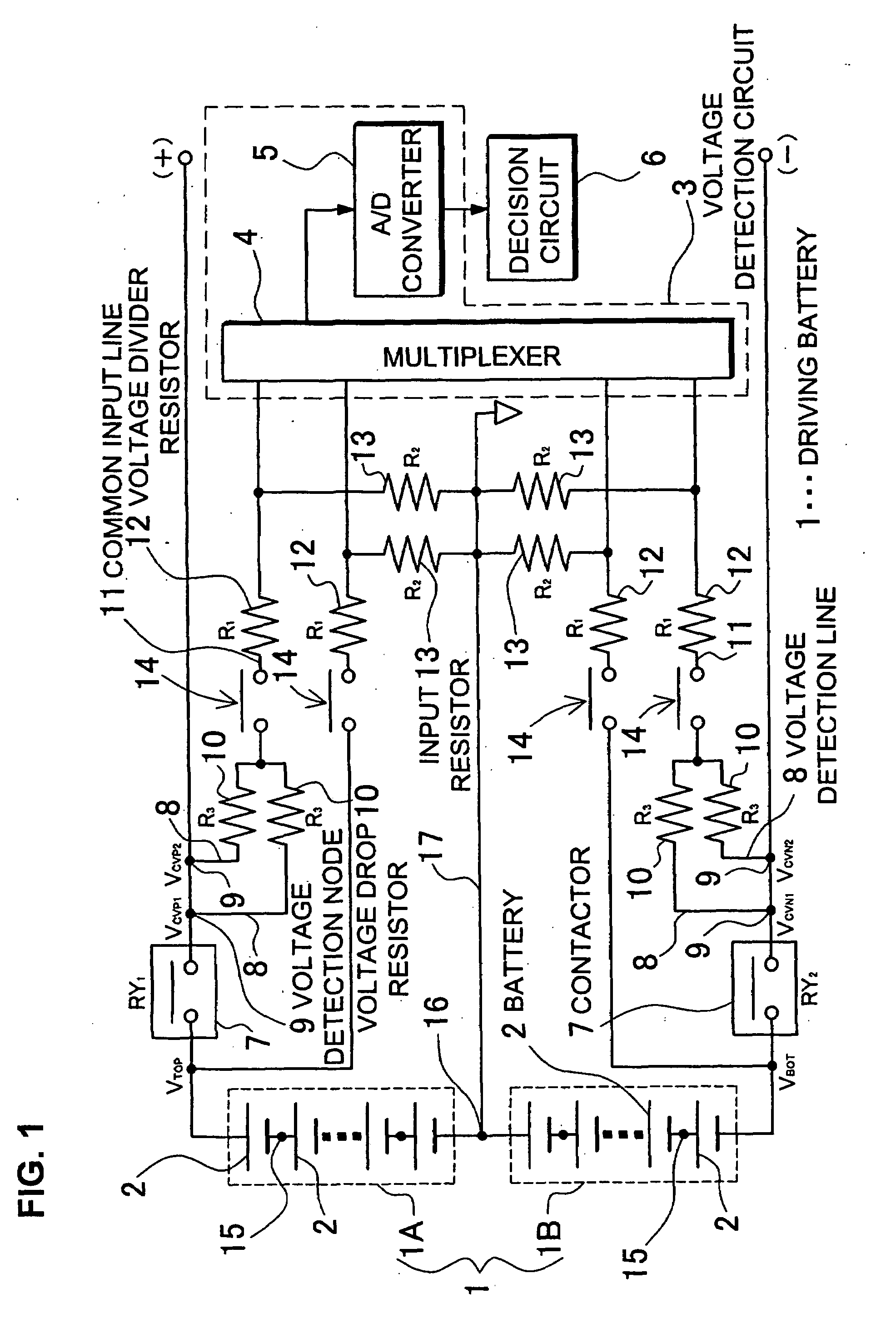
[0017]The car power source apparatus of the present invention is provided with a driving battery that supplies power to the car's electric motor, a voltage detection circuit that measures the voltage of batteries in the driving battery, a plurality of voltage detection lines connected in parallel between the input-side of the voltage detection circuit and driving battery voltage detection nodes, and a decision circuit that determines if a voltage detection line is open circuited from the voltage measured by the voltage detection circuit. Each voltage detection line has a voltage drop resistor connected in series. The voltage detection circuit is provided with input resistors on its input-side. The car power source apparatus computes voltage measured by the voltage detection circuit, which is from the voltage drop resistor and input resistor voltage divider, to determine voltage detection line open circuit.

[0018]In the car power source apparatus of the present invention, the positiv...


PUM


Abstract

The car power source apparatus is provided with a driving battery 1 that supplies power to the car's electric motor, a voltage detection circuit 3 that measures the voltage of batteries 2 in the driving battery 1, a plurality of voltage detection lines 8 connected in parallel between the input-side of the voltage detection circuit 3 and driving battery 1 voltage detection nodes 9, and a decision circuit 6 that determines if a voltage detection line 8 is open circuited from the voltage measured by the voltage detection circuit 3. Each voltage detection line 8 has a voltage drop resistor 10 connected in series. The voltage detection circuit 3 is provided with input resistors 13 on its input-side. The car power source apparatus makes computations on the voltage measured by the voltage detection circuit 3, which is from the voltage divider formed by the input resistor 13 and voltage drop resistors 10, to detect voltage detection line 8 open circuit.

Description

BACKGROUND OF THE INVENTION[0001]1. Field of the Invention[0002]This invention relates to a power source apparatus that powers a motor to drive an electric vehicle such as a hybrid car or electric automobile, and relates to a car power source apparatus having a simple circuit structure that can detect an open circuit in a voltage detection line for detecting battery module voltage.[0003]2. Description of the Related Art[0004]A power source apparatus that powers an electric vehicle detects battery voltage and controls charging and discharging to prevent over-charging and over-discharging of the driving battery. This is because over-charging and over-discharging degrade battery electrical characteristics and shorten battery lifetime. A car power source apparatus has been developed (Japanese Patent Application Disclosure 2006-25501) to prevent battery over-charging and over-discharging by detecting driving battery voltage and controlling battery charging and discharging.[0005]The car p...

Claims


Application Information

Patent Timeline
IPC IPC(8): H01M10/48B60L3/00
CPCH01M10/48B60L3/0038B60L3/0069B60L3/04B60L11/1853B60L11/1859Y02T10/7061B60L11/1864B60L2240/547B60L2240/549Y02T10/7044Y02T10/7005B60L11/1861B60L58/18B60L58/14B60L58/21B60L58/15Y02T10/70Y02E60/10
Inventor OOSAWA, TAKESHIFURUKAWA, KIMIHIKO
Owner SANYO ELECTRIC CO LTD
Why Eureka
Try Eureka