Filament transformer for x-ray tubes

a technology of filament transformer and x-ray tube, which is applied in the direction of transformer/inductance details, coils, electrical devices, etc., can solve the problems of large window space, bulky and voluminous x-ray machine options, and concentric design of filament transformers, etc., and achieve the effect of increasing creepage distan

Inactive Publication Date: 2008-04-03
GENERAL ELECTRIC CO
View PDF7 Cites 17 Cited by
  • Summary
  • Abstract
  • Description
  • Claims
  • Application Information

AI Technical Summary

Benefits of technology

[0009]The present invention provides a filament transformer for an X-ray tube. The filament transformer comprises: (a) a core; (b) a primary winding and a secondary winding wound around the core, wherein the secondary winding is biased at a high voltage and the primary winding is placed in line with the secondary winding; and (c) a shield for the primary winding. In an embodiment, the transformer further includes a bobbin for incorporating the primary winding and the secondary winding. An arrangement for increasing creepage distance is incorporated in the bobbin by providing a plurality of partitions on the bobbin. In addition to the modifying the creepage distance, these partitions provide the required clearance between the primary winding and the secondary winding in the form of a solid barrier along with the insulation medium around (which may be, for example, oil).
[0010]In another embodiment, a filament transformer for an X-ray tube is provided. The filament transformer comprises; (a) a core; (b) a primary winding and a secondary winding wound around the core, wherein the secondary winding is biased at a high voltage and the primary winding is placed in line with the secondary winding; and (c) a bobbin having a primary section incorporating the primary winding and a secondary section incorporating the secondary winding and at least one partition configured to be empty. In an embodiment, the partitions of the bobbin include a first partition provided on the secondary section of the bobbin adjacent to the primary section of the bobbin and a second partition provided on the secondary section of the bobbin adjacent to the core.

Problems solved by technology

The concentric design of the typical transformer windings discussed above requires substantial window space in the selection of the core.
For this reason, when it comes to the use of high-voltage transformers specially adapted for use in low power X-ray machines, which typically require light weight and compact packaging, the concentric design of the filament transformer becomes one of the bulky and voluminous option for the X-ray machine.

Method used


Image

  • Filament transformer for x-ray tubes
  • Filament transformer for x-ray tubes
  • Filament transformer for x-ray tubes

Examples


Embodiment Construction

[0020]In the following detailed description, reference is made to the accompanying drawings that form a part thereof, and in which is shown by way of illustration specific embodiments that may be practiced. These embodiments are described in sufficient detail to enable those skilled in the art to practice the embodiments, and it is to be understood that other embodiments may be utilized and that logical, mechanical, electrical and other changes may be made without departing from the scope of the embodiments. The following detailed description is, therefore, not to be taken as limiting the scope of the invention.

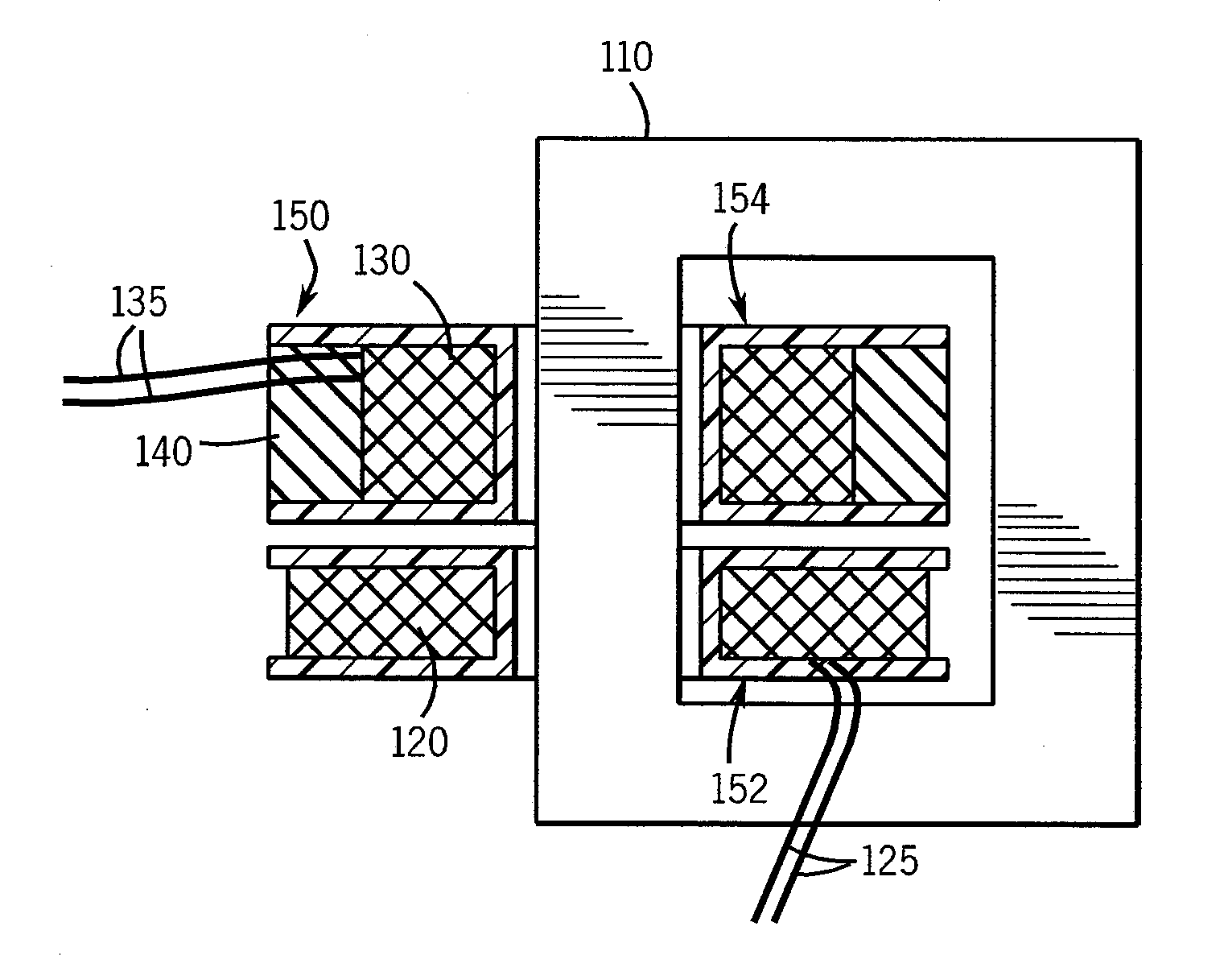
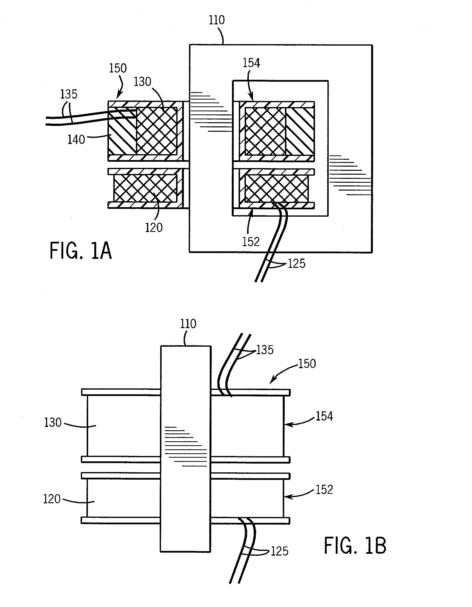
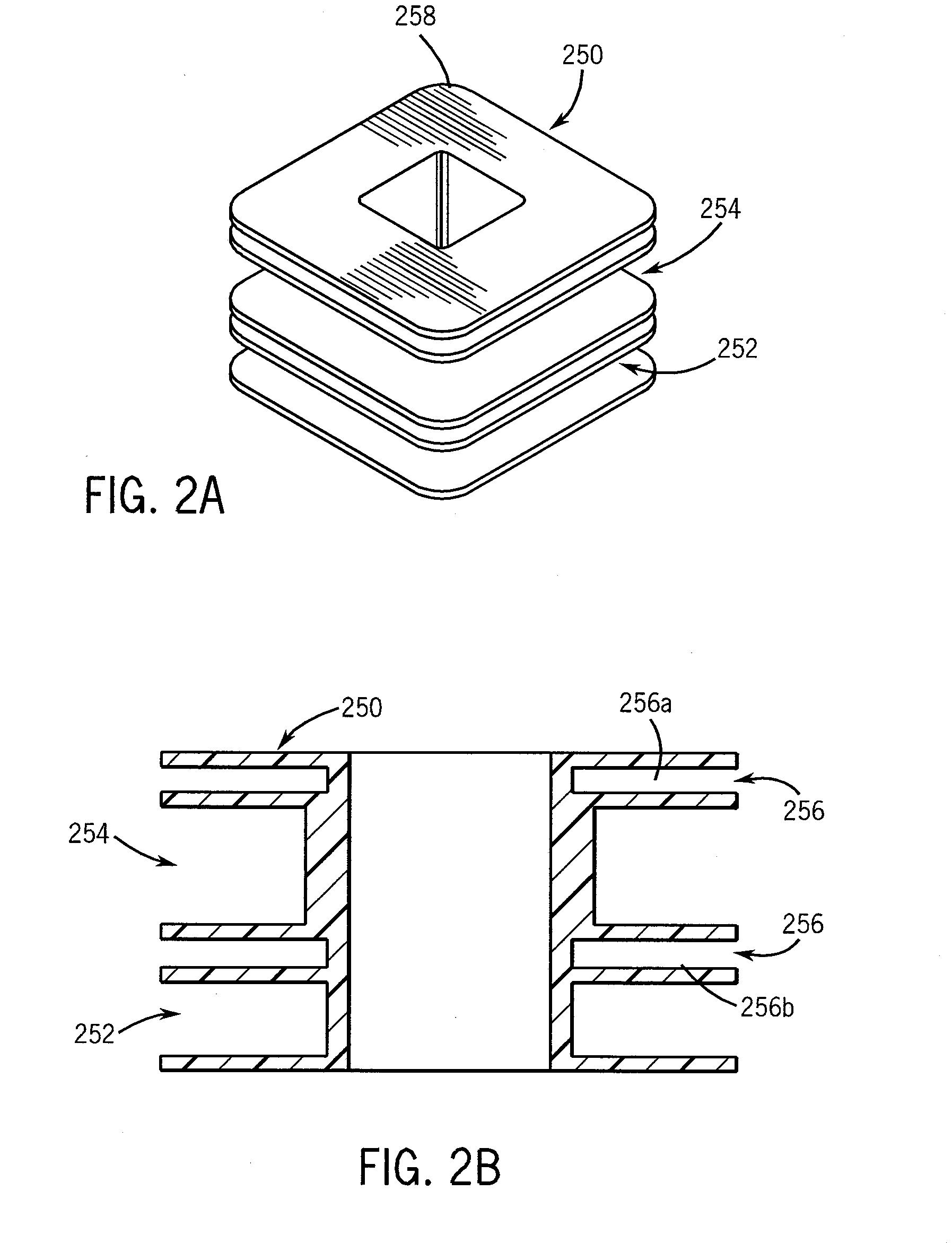
[0021]In various embodiments, a filament transformer for a bipolar X-ray tube including a secondary winding biased at a high voltage and a primary winding placed in line with the secondary winding on a magnetic core is provided. In an embodiment, the invention provides an arrangement for increasing creepage distance in compact transformers. More particularly, embodiments of t...


PUM

PropertyMeasurementUnit
diameteraaaaaaaaaa
voltageaaaaaaaaaa
insulatingaaaaaaaaaa

Abstract

The present invention provides an in-line filament transformer for a vacuum device. The filament transformer comprises: a core; a primary winding and a secondary winding wound around the core, wherein the secondary winding is biased at a high voltage and the primary winding is placed in line with the secondary winding; and a shield for shielding the primary winding. In an embodiment, the transformer comprises a bobbin for incorporating primary winding and secondary winding. An arrangement of increasing creepage distance is incorporated in the bobbin by providing plurality of sections on the bobbin. The invention also provides a shield in the primary section of the bobbin for shielding the primary winding from the secondary winding. In an embodiment the shield is in the form of shield winding of thin wires wound in a defined manner.

Description

FIELD OF THE INVENTION[0001]This invention generally relates to a transformer for a bipolar vacuum tube and more particularly to a filament transformer for an X-ray tube.BACKGROUND OF THE INVENTION[0002]In an X-ray machine, the X-ray tube is often a bipolar tube having an anode and a cathode maintained at a high voltage potential. The tube has a filament, a low resistance element, maintained close to the cathode potential and having a controllable current on the order of a few Ampere passing through it to sustain thermionic emission to drive the commanded X-ray tube current. This current is supplied by a filament transformer and the low resistance nature of the filament causes the required high current with application of a voltage on the order of Volts. Therefore, often a 1:1 or a step down design of transformer is used for this application, having primary number of turns equal or higher than the secondary number of turns. The secondary winding is biased to the cathode potential to...

Claims


Application Information

Patent Timeline
Patent Type & Authority Applications(United States)
IPC IPC(8): H01F27/28
CPCH01F27/289H01F27/325H01F2005/022H01F27/38H05G1/10
Inventor SUNDARAM, SENTHIL KUMAR
Owner GENERAL ELECTRIC CO
Why Eureka
Try Eureka