Imaging device

a technology of imaging device and focusing device, which is applied in the direction of printers, cameras, instruments, etc., can solve the problem of difficulty in sufficiently reducing the size of imaging devi

Inactive Publication Date: 2008-04-03
FUJI PHOTO OPTICAL CO LTD
View PDF23 Cites 29 Cited by
  • Summary
  • Abstract
  • Description
  • Claims
  • Application Information

AI Technical Summary

Benefits of technology

[0014]With this configuration, the third actuator that relatively moves the imaging optical system in the optical axis direction with respect to the moving member, which is moved in the first direction

Problems solved by technology

For this reason, it is difficult to sufficiently reduce in size the imaging device t

Method used


Image

  • Imaging device
  • Imaging device
  • Imaging device

Examples


Embodiment Construction

[0020]An embodiment of the invention will be described below with reference to the accompanying drawings. Like reference symbols will be affixed to like elements in the description of the drawings, and their redundant explanation will be omitted.

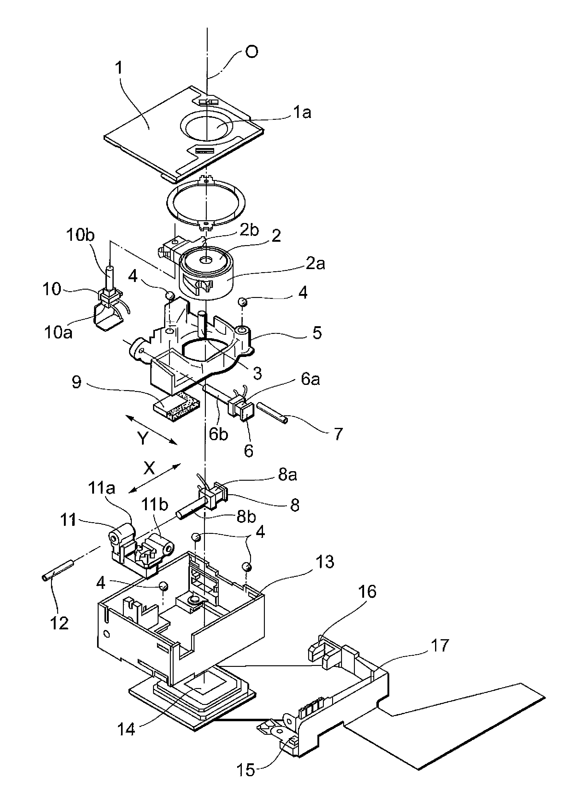
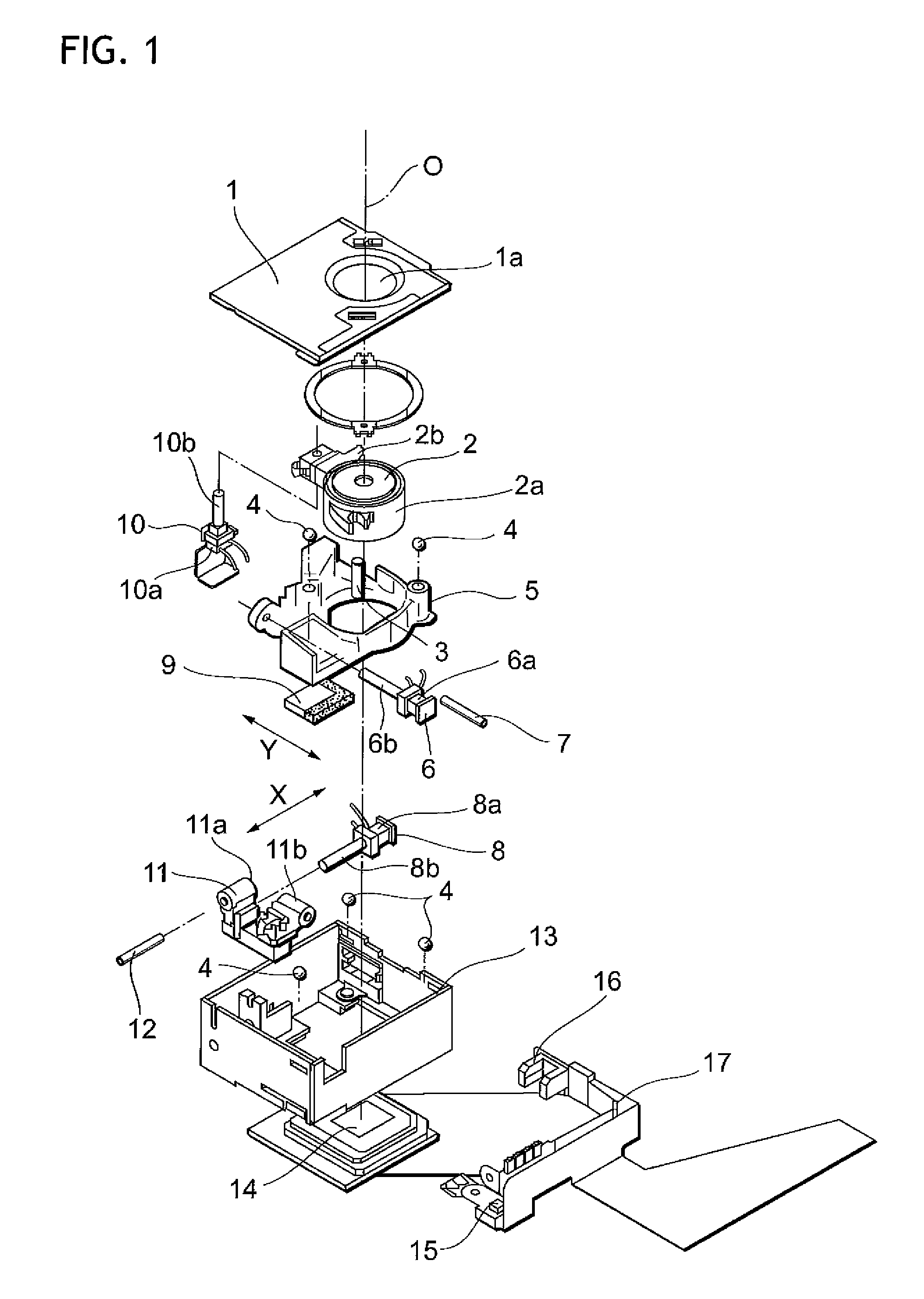
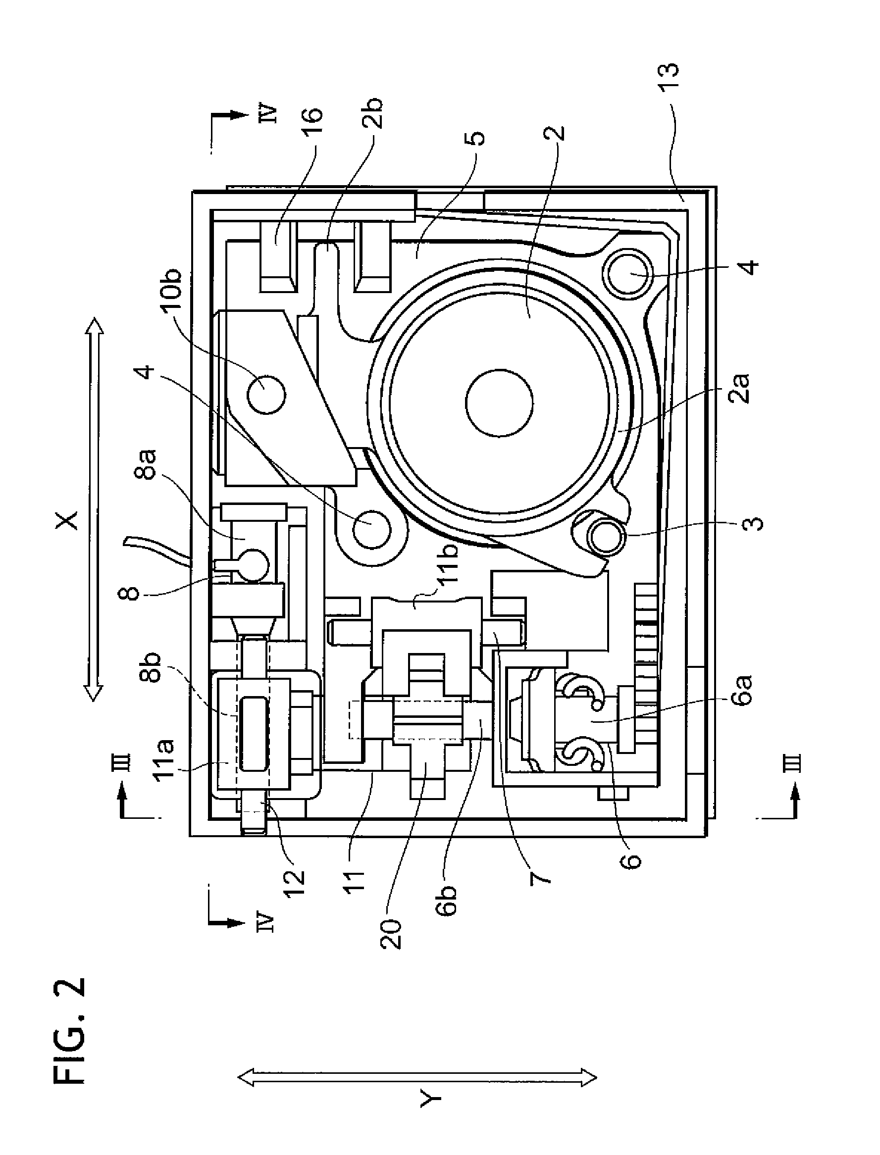
[0021]FIG. 1 is an exploded perspective view showing an imaging portion, a camera-shake compensation mechanism and a zooming mechanism of an imaging device according to an embodiment of the invention. FIG. 2 is a plan view of the imaging portion, the camera-shake compensation mechanism and the zooming mechanism of the imaging device in FIG. 1. FIG. 3 is a section view taken along III-III in FIG. 2. FIG. 4 is a section view taken along IV-IV in FIG. 2.

[0022]The imaging device according to this embodiment makes camera shake compensation by relatively moving an imaging optical system and an imaging element in directions perpendicular to an optical axis direction. In other words, the camera shake is compensated by moving the imaging optical syst...


PUM


Abstract

An imaging device for making camera shake compensation by relatively moving an imaging optical system and an imaging element in directions perpendicular to an optical axis direction, includes first to third actuators and a moving member. The first actuator relatively moves the imaging optical system and the imaging element in a first direction perpendicular to the optical axis direction. The second actuator 6 relatively moves the imaging optical system and the imaging element in a second direction which is perpendicular to the optical axis direction and which intersects the first direction. The second actuator is attached to the moving member. The moving member is moved by an action of the first actuator and an action of the second actuator in the first direction and the second direction. The third actuator relatively moves the imaging optical system and the moving member in the optical axis direction.

Description

CROSS-REFERENCE TO RELATED APPLICATIONS[0001]This application is based upon and claims the benefit of priority from the Japanese Patent Application No. 2006-268723 filed on Sep. 29, 2006, the entire contents of which are incorporated herein by reference.BACKGROUND OF THE INVENTION[0002]1. Technical Field[0003]The invention relates to an imaging device used in shooting.[0004]2. Description of the Related Art[0005]JP Hei. 10-39350 A discloses an imaging device which has a function of compensating camera shake during shooting, for use in a camera, a video camera and a camera installed in a cellular phone and which can perform zooming and focusing. This imaging device performs zooming and focusing by integrally moving the imaging optical system and the camera shake compensation mechanism in the optical axis direction.[Patent Literature 1] JP Hei. 10-39350 A[Patent Literature 2] JP 2005-309209 A[Patent Document 3] JP 2005-331399 A[0006](corresponding to U.S. Pat. No. 7,132,824)[0007]Howe...

Claims


Application Information

Patent Timeline
IPC IPC(8): H04N5/228
CPCG02B5/3025G02B27/646H04N5/23248H04N5/2253H04N5/2254G03B17/02G03B3/10G03B5/00G03B2205/0061H04N23/55H04N23/54H04N23/68H04N23/00
Inventor SUZUKI, YUSUKE
Owner FUJI PHOTO OPTICAL CO LTD
Why Eureka
Try Eureka