
Objective lens for endoscope, and imaging apparatus for endoscope using the same

a technology of endoscope and imaging apparatus, applied in the field of objective lenses, can solve the problems of difficult to obtain a sufficient back focus, affecting the image quality of the endoscope, and causing blur or ghost, etc., and achieve the effect of excellent observation imag

Inactive Publication Date: 2008-04-03
FUJI PHOTO OPTICAL CO LTD
View PDF1 Cites 24 Cited by
  • Summary
  • Abstract
  • Description
  • Claims
  • Application Information

AI Technical Summary

Benefits of technology

"The invention is an endoscope objective lens that can correct both axial and lateral chromatic aberration while ensuring a long back focus for placement of an optical-path deflecting prism. The lens system includes a front-group divergent lens system, an aperture diaphragm, and a rear-group convergent lens system. The front-group divergent lens system has negative lenses, while the rear-group convergent lens system has a positive third lens, a positive cemented lens, and a negative fifth lens. The objective lens satisfies conditional expressions to achieve an excellent observation image. The imaging apparatus for endoscope using this objective lens can obtain a high-resolution image signal."

Problems solved by technology

When a sufficient margin is not provided to the distance between a wall surface of the prism and the effective light flux, however, flare or ghost is caused.
In an endoscope objective lens, in order to cope with the request for a wider angle, however, the focal length tends to be shorter even when the image size is identical, and therefore it is difficult to obtain a sufficient back focus.
In the configuration of JP-A-10-260348, however, correction of lateral chromatic aberration is insufficient as compared with that of axial chromatic aberration, and therefore the correction balance between axial chromatic aberration and lateral chromatic aberration is requested to be improved.

Method used


Image

  • Objective lens for endoscope, and imaging apparatus for endoscope using the same
  • Objective lens for endoscope, and imaging apparatus for endoscope using the same
  • Objective lens for endoscope, and imaging apparatus for endoscope using the same

Examples


examples

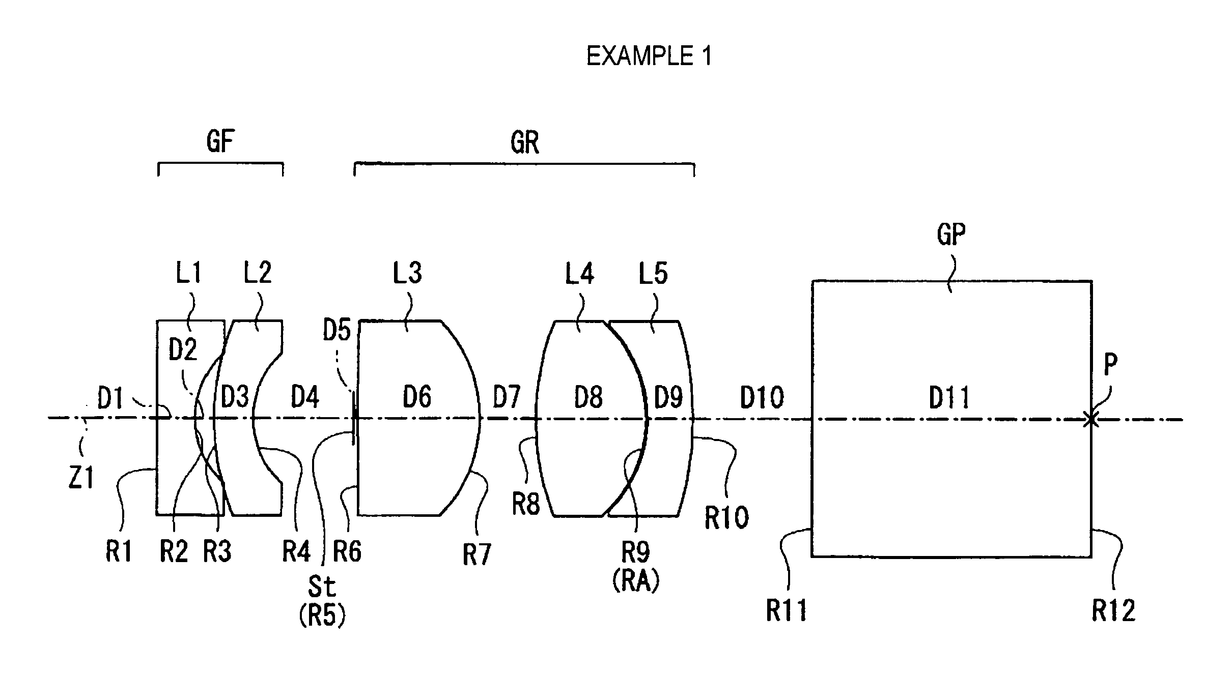
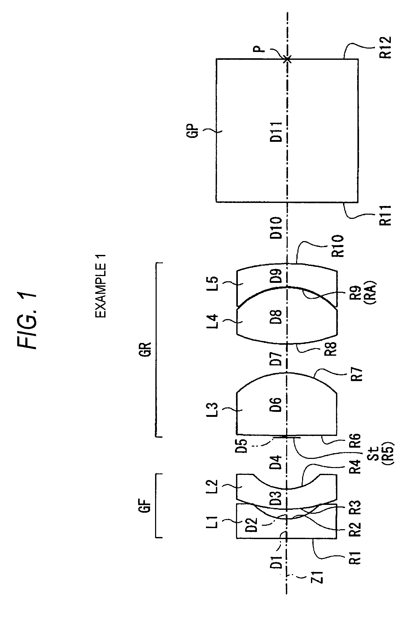
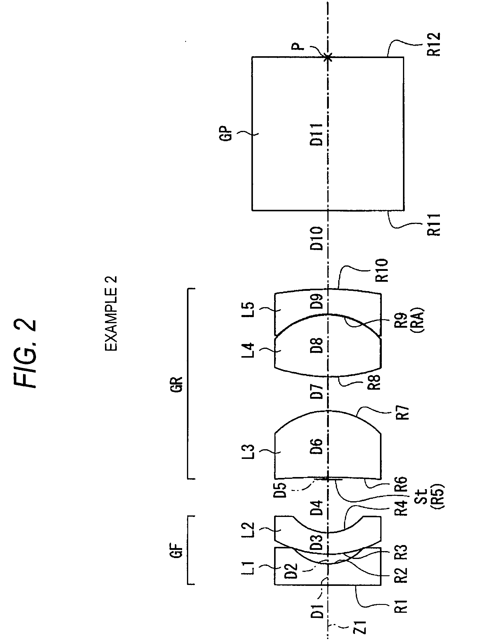
[0079]Next, specific numerical examples of the endoscope objective lens of the embodiment will be described. Hereinafter, the first to sixth numerical examples (Examples 1 to 6) will be collectively described.

[0080]FIG. 8 shows lens data of an endoscope objective lens of Example 1. In the column of the surface number Si in the lens data shown in FIG. 8, the number of an i-th (i=1 to 12) surface which is numbered in such a manner that the surface of a component that is closest to the object side is set as the first surface, and the number is more sequentially increased as further advancing toward the image side is shown. In the column of the radius of curvature Ri, the value (mm) of the radius of curvature of the i-th surface counted from the object side is shown in correspondence to the reference character Ri used in FIG. 1. Also in the column of the on-axis surface spacing Di, the separation (mm) on the optical axis between an i-th surface Si counted from the object side and an (i+...


PUM


Abstract

A front group consists of two concave lenses. A rear group consists of: a positive lens in which the object-side surface has a larger radius of curvature; and a cemented lens configured by a positive lens in which the object-side surface has a larger radius of curvature, and a negative meniscus lens, the cemented lens having being positive as a whole. An objective lens satisfies the following conditional expressions:|dx / fF|≧3.0   (1)(f / f3)×ν3<23   (2)f2×(ν5−ν4) / {RA×(Bf+d5 / n5)}>7   (3)where dx is the distance between the groups, f, fF, and f3 are the focal lengths of the objective lens, the front group, and the lens, respectively, ν3, ν4, and ν5 are the Abbe numbers of the lenses, RA is the radius of curvature of the cementing surface between the lenses, Bf is the back focus, and d5 and n5 are the center thickness and refractive index with respect to the d-line of the lens.

Description

BACKGROUND OF THE INVENTION[0001]1. Field of the Invention[0002]The present invention relates to an objective lens which is to be disposed in a tip end portion of an endoscope, more particularly to an objective lens for endoscope (hereinafter, often referred to as endoscope objective lens) in which an optical-path deflecting prism is placed on the side of the image-side surface, and also to an imaging apparatus for endoscope using it.[0003]2. Description of the Related Art[0004]In the related art, as a direct-view type endoscope using a solid-state image pickup device such as a CCD (Charge Coupled Device), an endoscope in which a solid-state image pickup device is placed in a tip end portion parallel to the axial direction is known. In such an endoscope, usually, a prism for deflecting the optical path is inserted and placed via a cover glass and the like between the solid-state image pickup device and an objective lens. The size of the optical-path deflecting prism depends on the i...

Claims


Application Information

Patent Timeline
Patent Type & Authority Applications(United States)
IPC IPC(8): G02B21/02
CPCG02B23/243
Inventor MIYANO, HITOSHI
Owner FUJI PHOTO OPTICAL CO LTD
Learn More