
Screw for plastic articles

a screw and plastic article technology, applied in the direction of screws, threaded fasteners, fastening means, etc., can solve the problems of increasing manufacturing costs, affecting the quality of plastic articles, etc., to achieve low cost, high tightening force, and low disqualification ratio

Inactive Publication Date: 2008-04-03
M & W FASTENER
View PDF1 Cites 37 Cited by
  • Summary
  • Abstract
  • Description
  • Claims
  • Application Information

AI Technical Summary

Benefits of technology

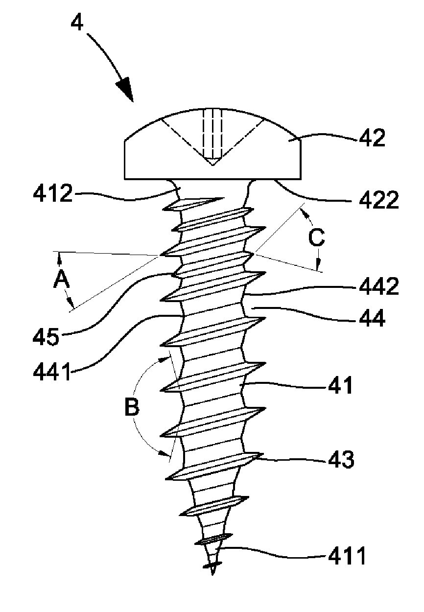
The present invention provides a screw for plastic articles that can be manufactured at low cost and low ratio of disqualified products while providing high tightening force and low insertion torque for rapid fastening. The screw has a unique design with a first thread and a second thread. The first thread is formed on the shank and has a plurality of convolutions, while the second thread is formed on the coupling end of the shank and intermediate the convolutions of the first thread. The first thread has a root defined between two adjacent crests and has a profile defined by two straight lines that form an angle of 120-160 degrees therebetween. The second thread has a thread angle of 35-65 degrees. The technical effects of the invention include low cost manufacturing, high tightening force, and low insertion torque.

Problems solved by technology

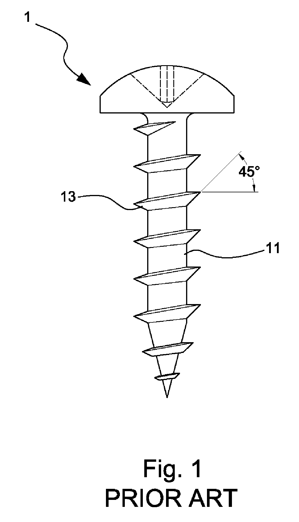
However, the materials of the plastic articles are liable to be damaged by the steep flanks of the thread 13.
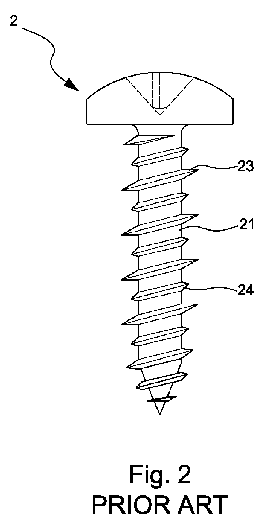
However, the entry speed of the screw 2 into the plastic articles is slow, as the screw 2 has a high friction coefficient due to large number of convolutions of the threads 23 and 24.
Hence, skew heads occur easily, leading to an increase in the manufacturing cost, as the ratio of disqualified products is high.

Method used


Image

  • Screw for plastic articles
  • Screw for plastic articles
  • Screw for plastic articles

Examples


Embodiment Construction

[0028]FIG. 4 illustrates an example of a screw 4 in accordance with the present invention. The screw 4 comprises a shank 41 and a head 42 on an end of the shank 41. FIG. 5 shows a blank 40 for forming the screw 4.

[0029]The shank 41 comprises an insertion end 411 for penetrating a plastic article or the like. The shank 41 further comprises a coupling end 412 for engaging with the plastic article. In this example, the insertion end 411 has a pointed end. In another example, the insertion end 411 may be of drill bit type, as shown in FIG. 10. In a further example, the insertion end 411 may have a flat end face, as shown in FIG. 11. The coupling end 412 includes an engaging section adjacent to the bottom face 422 of the head 42. An axial length of the engaging section of the coupling end 412 can be adjusted according to the length of the screw 4.

[0030]A first thread 43 is formed on an outer circumference of the shank 41 from the coupling end 412 through the insertion end 411. The first ...


PUM

PropertyMeasurementUnit
angleaaaaaaaaaa
thread angleaaaaaaaaaa

Abstract

A screw for plastic articles includes a head, a shank having an insertion end and a coupling end adjacent to a bottom face of the head, a first thread, and a second thread. The first thread is formed on the shank and extends from the insertion end through the coupling end of the shank. The first thread includes a plurality of convolutions. The second thread is formed on the coupling end of the shank and intermediate the convolutions of the first thread. The second thread has a major diameter smaller than that of the first thread. The first thread includes a plurality of crests. A root is defined between two adjacent crests of the first thread outside the coupling end and has a profile defined by two straight lines that forms an angle of 120-160 degrees therebetween.

Description

BACKGROUND OF THE INVENTION[0001]1. Field of the Invention[0002]The present invention relates to a screw and, more particularly, a self-tapping screw for fastening plastic articles.[0003]2. Description of the Related Art[0004]Screws for widely used plastic articles requires easy, reliable fastening without causing damage to the plastic articles. Hence, screws for fastening plastic articles generally include: (1) large thread height for providing sufficient engaging depth for the purposes of preventing disengagement, (2) large pitch for preventing disintegration of the materials of the plastic articles under the pressure of the screw threads, and (3) small thread angle to allow easy, rapid insertion of the screw into the plastic articles without the need of applying a large torque to the screw.[0005]FIG. 1 illustrates a conventional screw 1 for plastic articles. The screw 1 includes a shank 11 on which a continuous, asymmetric thread 13 is formed. The thread 13 has an acute thread an...

Claims


Application Information

Patent Timeline
Patent Type & Authority Applications(United States)
IPC IPC(8): F16B35/04
CPCF16B25/0015F16B25/0047F16B25/10F16B25/0068F16B25/0057
Inventor WU, MARTIN S.H.
Owner M & W FASTENER
Learn More