Eureka AIR delivers breakthrough ideas for toughest innovation challenges, trusted by R&D personnel around the world.

External coil assembly for implantable medical prostheses

Active Publication Date: 2008-04-03
CORTIGENT INC
View PDF17 Cites 15 Cited by
  • Summary
  • Abstract
  • Description
  • Claims
  • Application Information

AI Technical Summary

Benefits of technology

[0021]According to a fifth aspect of the present disclosure, a method to improve receiving sensitivity in an external coil assembly for an inductively coupled implant on the human or animal body is disclosed, wherein the external coil assembly comprises a transmitting coil and a receiving coil, the implant comprises an implant coil, the transmitting coil allows transmission of a forward telemetry signal at a carrier frequency to the implant, and the implant is adapted to send a back telemetry signal to the external coil assembly, the method comprising: adjusting position of the receiving coil with respect to the transmitting coil to reduce influence of a noise signal at the carrier frequency received by the external coil assembly in addition to the back telemetry signal.
[0023]In accordance with the present disclosure, the back telemetry signals sent by the implant are reliably retrieved in the presence of a strong magnetic field imposed by the RF carrier of the power transmitter, without increasing the complexity of the receiver circuits and compromising the cosmetics of mechanical configuration of the external coils.

Problems solved by technology

Due to the low power nature of the implant device and the limited implant coil size, it imposes difficulties to retrieve the low level feedback signals at the external side in the presence of a strong magnetic field created by the external transmitting power carrier.
In the case of retinal prosthesis when the implant coil is mechanically linked to the eyeball, the eyeball movement compromises the coupling condition between the external and implant coils and therefore makes the back telemetry signal condition at the external receiving end worse.
While some of these early attempts met with some limited success, these early prosthetic devices were large, bulky and could not produce adequate simulated vision to truly aid the visually impaired.

Method used


Image

  • External coil assembly for implantable medical prostheses
  • External coil assembly for implantable medical prostheses
  • External coil assembly for implantable medical prostheses

Examples


Embodiment Construction

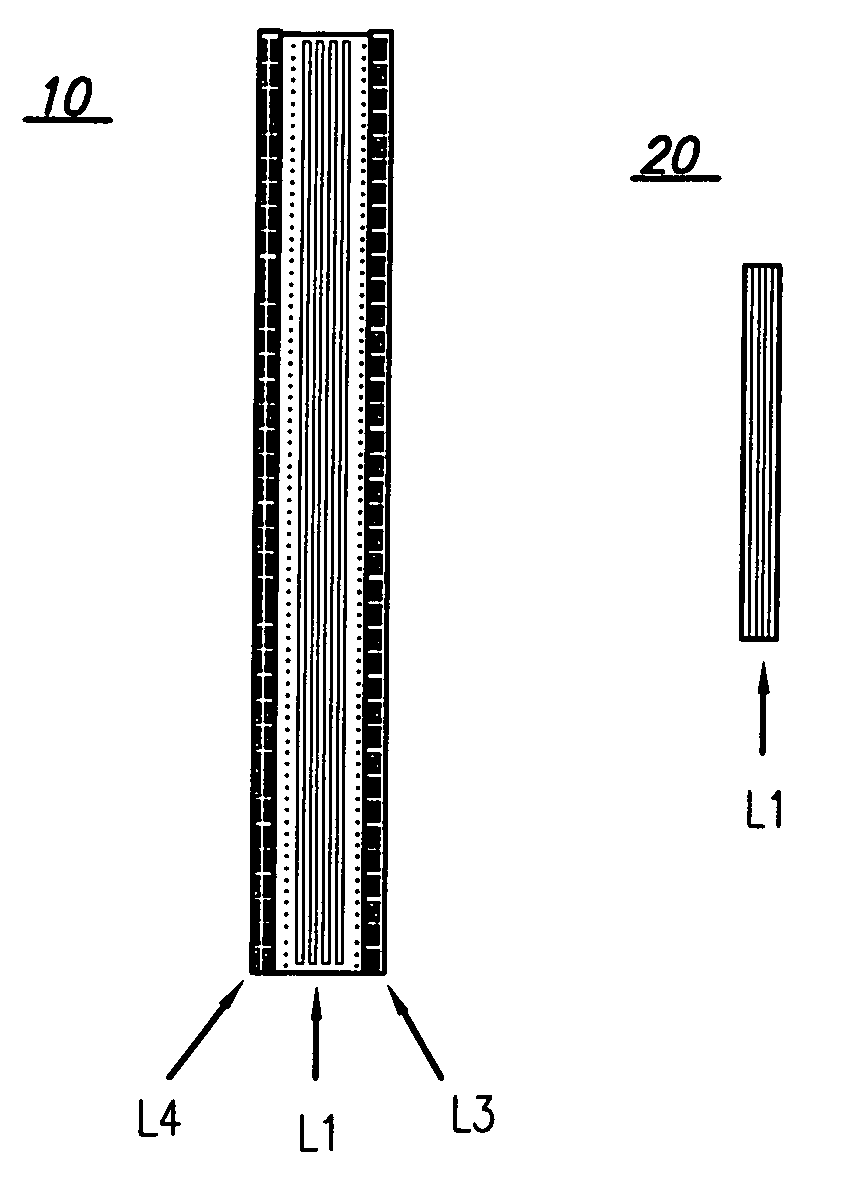
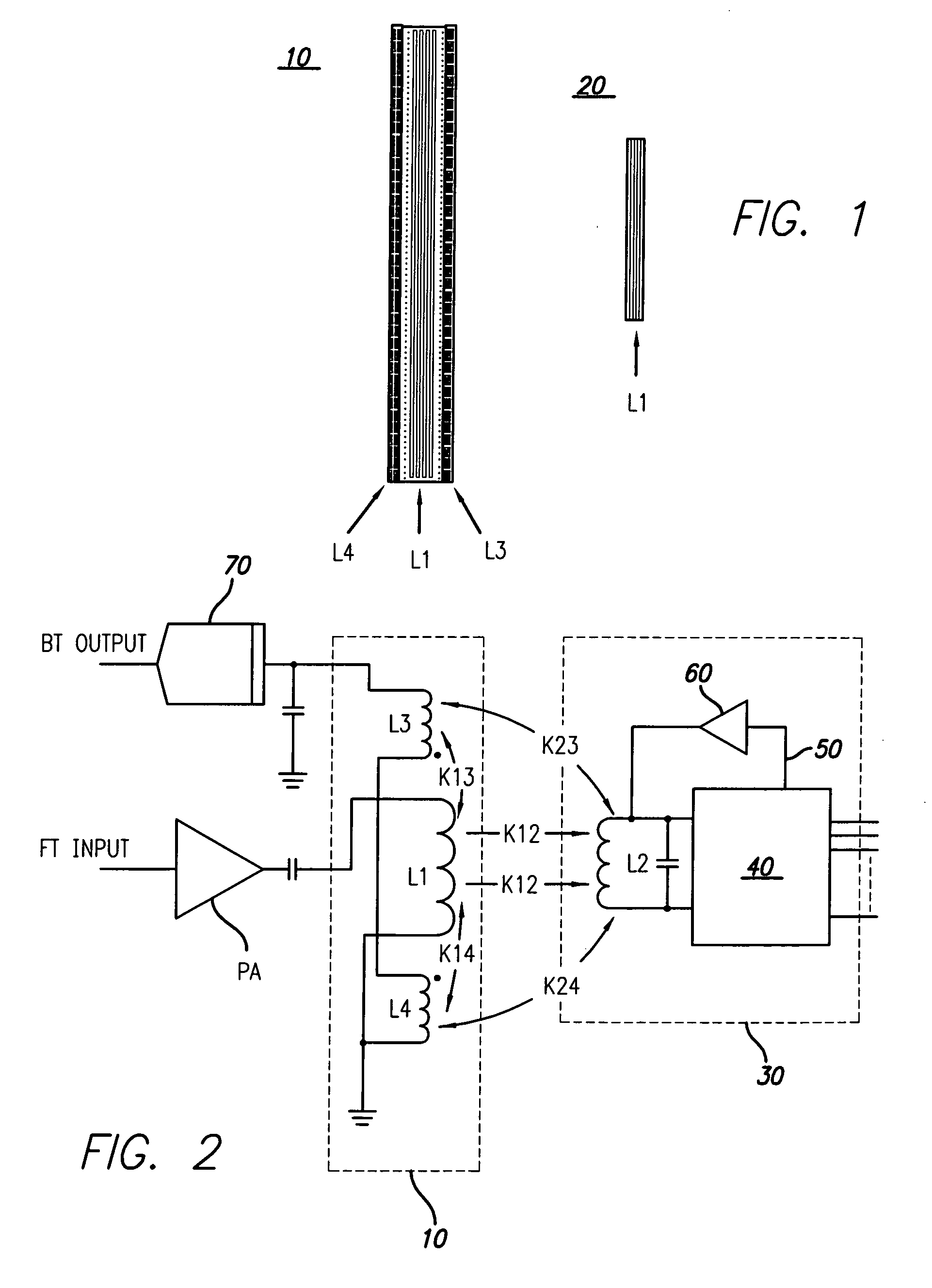
[0032]FIG. 1 shows a first embodiment of an external coil assembly 10 inductively coupled with an implant coil 20. The external coil assembly 10 comprises inductors L1, L3 and L4. The implant coil 20 comprises inductor L2. Throughout the present specification, the various inductors will be described as coils, for exemplary purposes.

[0033]With reference to the external coil assembly 10, coil L1 represents a transmitting coil, and coils L3, L4 represent receiving coils. Transmitting coil L1 allows a forward telemetry (FT) signal to be sent to implant coil 20 or L2. Receiving coils L3 and L4 allow a back telemetry (BT) signal to be received from the implant coil 20 or L2. The concept of FT signals and BT signals is known to the person skilled in the art. See, for example, U.S. Pub. App. No. 2005 / 0288734 (Visual Prosthesis with Operational Data Telemetry), incorporated herein by reference in its entirety. In accordance with this embodiment, transmitting coil L1 is located between receiv...


PUM


Abstract

Methods and devices for inductively coupled implants on the human or animal body are disclosed. An external coil assembly to be used with the implant has a transmitting coil and one or more receiving coils. The number of the receiving coils, their distance from the transmitting coil and their shape is chosen to reduce the influence of a noise signal received by the external coil assembly.

Description

FEDERALLY SPONSORED RESEARCH[0001]This invention was made with government support under grant no. R24EY12893-01, awarded by the National Institutes of Health. The U.S. Government has certain rights in the invention.CROSS REFERENCE TO RELATED APPLICATIONS[0002]The present invention is related to U.S. Pub. App. No. 2005 / 0222624 (Retinal Prosthesis with Side Mounted Inductive Coil) and U.S. Pub. App. No. 2005 / 0288734 (Visual Prosthesis with Operational Data Telemetry), the disclosures of both of which are incorporated herein by reference in their entirety.BACKGROUND[0003]1. Field[0004]The present disclosure relates to devices implantable on the animal or human body. In particular, it relates to an external coil assembly for implantable medical prostheses.[0005]2. Related Art[0006]In inductively powered retinal prostheses, coils are used to transmit and receive RF power in both external and implant ends. Reference can be made, for example, to U.S. Pat. No. 5,935,155 (Visual Prosthesis a...

Claims


Application Information

Patent Timeline
IPC IPC(8): A61N1/00
CPCA61N1/36046A61N1/3787A61N1/37229H04B5/263H04B5/72H04B5/79H04B5/43
Inventor DAI, RONGQINGZHOU, DAO MINGREENBERG, ROBERT J.GORD, JOHN
Owner CORTIGENT INC
Why Eureka
Eureka Blog
Learn More