
Precise droplet injection for calibrating a gas chromatography instrument

a gas chromatograph and precise technology, applied in the direction of instruments, liquid transfer devices, transportation and packaging, etc., can solve the problems of syringes being fragile, dangerous to use, and the calibration of gas chromatograph instruments

Inactive Publication Date: 2008-04-10
ELECTRONICS SENSOR TECH
View PDF10 Cites 5 Cited by
  • Summary
  • Abstract
  • Description
  • Claims
  • Application Information

AI Technical Summary

Benefits of technology

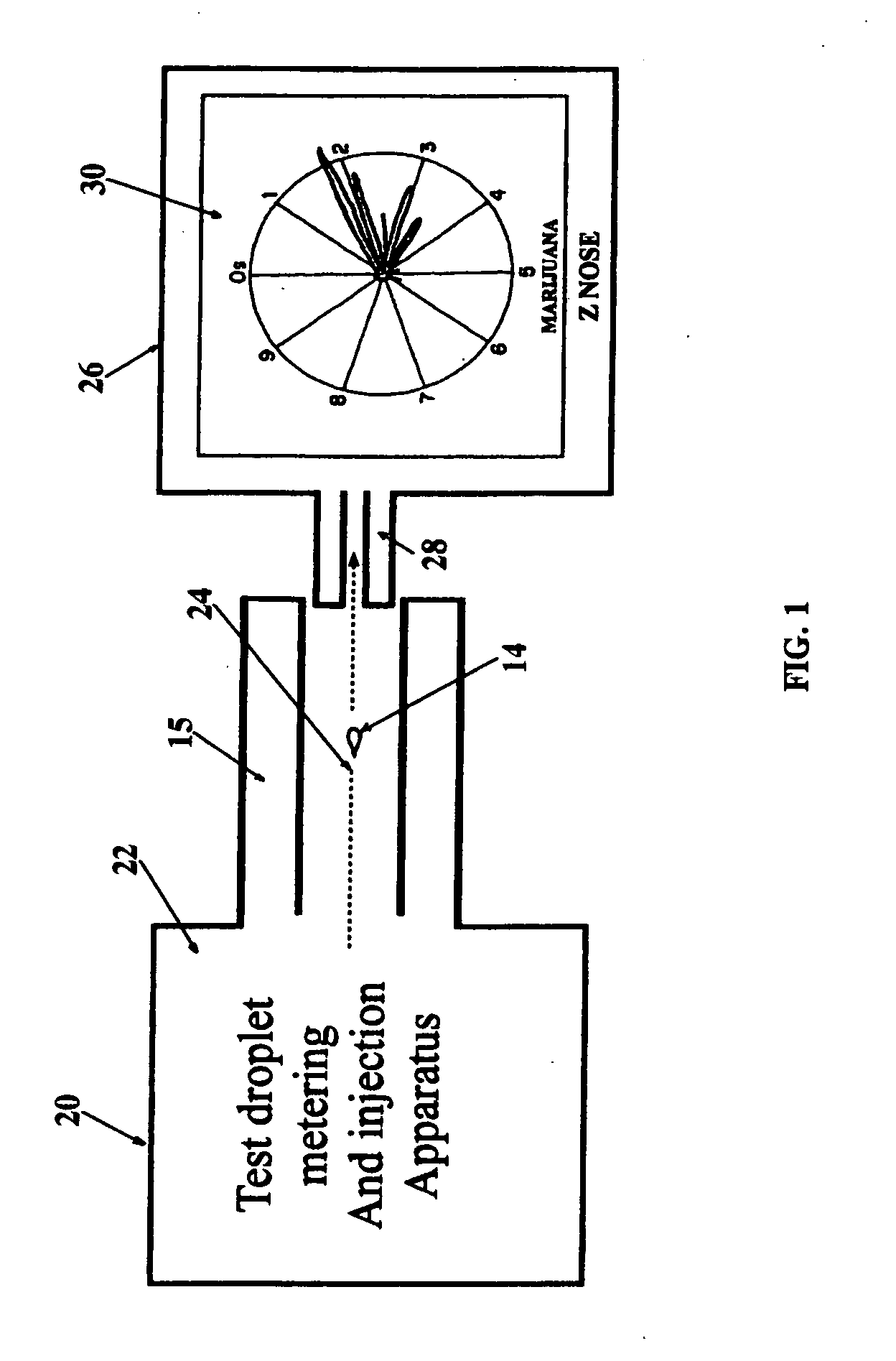
[0010]The purpose of the present invention is to allow the precise introduction of a diluted sample compound into an instrument which measures that compound for the purpose of calibration of the instrument. According to the invention a sample droplet of a known compound is forcefully shot into the inlet or throat of the instrument. Only the sample contacts the instrument inlet, and the injecting apparatus or device does not. Thus the present invention eliminates use of the hard to master injection by syringe, and prevents subsequent contamination of the precision instrument.
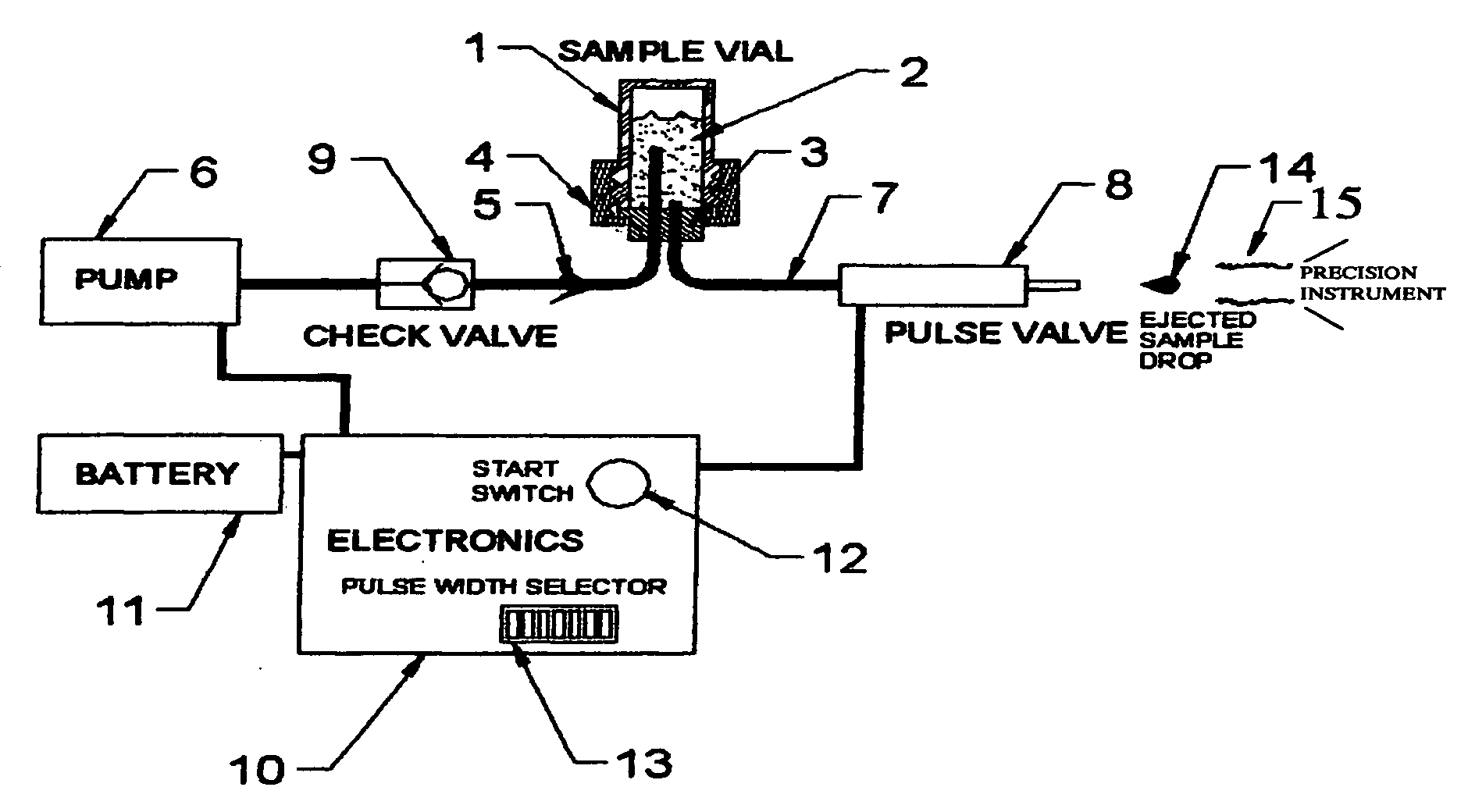
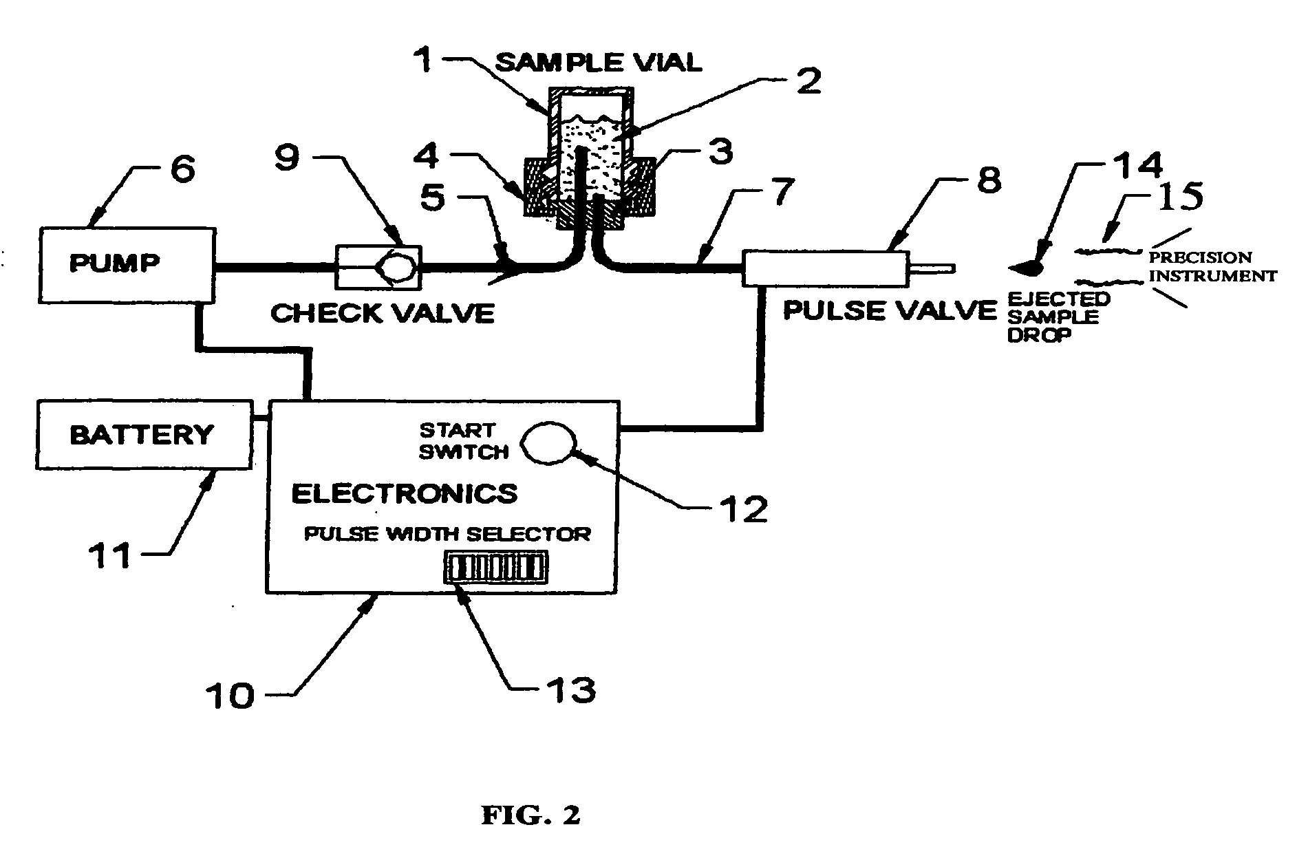
[0011]According to the presently preferred apparatus of the invention a single sample droplet with a precisely measured volume is supplied through a pulse valve to a precise target. The test apparatus is aligned in place both axially and angularly to assure that the droplet moves along an accurate coaxial trajectory into the throat of the precision instrument. A flexible boot is used to correctly interface between the droplet generator and the chromatograph, so that any wavering of the operator's hand will not adversely affect the trajectory of the droplet to be injected. Droplet generator action is initiated by a manual control and is otherwise automatic.

Problems solved by technology

The calibration of a gas chromatograph instrument, however, poses a somewhat different problem.
Syringes are fragile and are dangerous to use because of the sharp needle.
It is also difficult for an operator to control the syringe for accurately aiming the droplet into the inlet or throat of the machine.
Mis-direction of the droplet may cause contamination of the precision chromatography instrument and thus adversely affect the accuracy of its subsequent measurements.

Method used


Image

  • Precise droplet injection for calibrating a gas chromatography instrument
  • Precise droplet injection for calibrating a gas chromatography instrument
  • Precise droplet injection for calibrating a gas chromatography instrument

Examples


Embodiment Construction

FIGS. 2-4

[0048]Reference is now made to FIG. 2 which illustrates the electro-mechanical apparatus of the invention in a block and line form. The purpose of the present invention is for precise introduction of a diluted sample compound into an instrument 26 which measures that compound for the purpose of calibration of the instrument. According to the invention a sample droplet 14 of a known compound is forcefully shot into the inlet or throat 28 of the instrument 26. Only the sample droplet 14 contacts the instrument inlet, and the injecting apparatus or device does not. Thus the present invention eliminates use of the hard to master injection by syringe, and prevents subsequent contamination of the precision instrument. A vial or tank 1 holds the liquid 2 from which a sample is to be taken. The otherwise open bottom end of the vial or tank 1 is closed by a stopper 3 which, however, is pierced by two different sections of tubing that communicate with the interior of the tank or vial...


PUM

PropertyMeasurementUnit
flexibleaaaaaaaaaa
gas chromatographyaaaaaaaaaa
chemical constituentsaaaaaaaaaa

Abstract

A method and apparatus for calibrating a gas chromatography instrument by forcefully shooting a measured droplet which securely passes through a confined passageway without direct intervention of human hands into the entry throat of the instrument so as to avoid contaminating the apparatus or impairing the accuracy of the instrument.

Description

PRIORITY CLAIM[0001]This application claims priority of our Provisional Application Ser. No. 60 / 850,197 filed Oct. 5, 2006.FIELD OF INVENTION[0002]Gas chromatography instruments and the procedures for calibrating them.PRIOR ART[0003]Prior art patents include:[0004]Staples and Watson U.S. Pat. No. 5,289,715, issued 1994.[0005]Staples U.S. Pat. No. 6,212,938 issued 2001.[0006]Johnson et al U.S. Pat. No. 6,983,636 issued in 2006.BACKGROUND OF THE INVENTION[0007]Controlling and measuring very small quantities of fluid is required in many environments and for many purposes. For example, medical testing procedures as shown in the Johnson et al U.S. Pat. No. 6,983,636 issued in 2006 may require the repetitious application of droplets of identical size. Ink-jet printers require precise control of the flow of very small droplets of ink into their various output openings, and may utilize techniques such as those shown in the Starr U.S. Pat. No. 4,818,706 issued in 1989 or the Shimano U.S. Pat...

Claims


Application Information

Patent Timeline
Patent Type & Authority Applications(United States)
IPC IPC(8): G01N30/00
CPCG01N30/8665G01N30/24
Inventor WATSON, GARY W.PEARCE, ROBERT E.MOTIWALA, SALIN M.ZUHDE, FRANK E.
Owner ELECTRONICS SENSOR TECH
Learn More