Apparatus for and Method of Dosing a Wastewater Treatment System

a wastewater treatment system and apparatus technology, applied in water/sewage treatment by oxidation, separation processes, filtration separation, etc., can solve the problems of deterioration of the activeness of the agent, exposing the person handling the agent to potentially hazardous chemicals, and causing great harm to nearby living organisms, etc., to achieve the effect of reducing the cost of the treatment, ensuring the effect of safety

Inactive Publication Date: 2008-04-10
HOOT AEROBIC SYST
View PDF17 Cites 3 Cited by
  • Summary
  • Abstract
  • Description
  • Claims
  • Application Information

AI Technical Summary

Benefits of technology

[0015]The invention provides improved elements and arrangements thereof, for the purposes described, which are inexpensive, dependable and effective in accomplishing intended purposes of the invention.

Problems solved by technology

Unfortunately, the aerobic and anaerobic processes involved in breaking down the effluent do not reduce pathogens that, if discharged, could cause great harm to the nearby living organisms.
A drawback to this method is exposing the person handling the agent to potentially hazardous chemicals.
Another drawback is the deterioration of the activeness of the agent when exposed to ambient conditions, such as humidity.
However, tablets are problematic because they tend to absorb moisture and disintegrate, especially in wastewater treatment plants, thus do not store well or readily advance for use.
See, for example, U.S. Pat. No. 5,405,540, issued Apr. 11, 1995, to N. Tang. However, a significant drawback of dissolve / erosion-type feeders is, because granule / tablet dissolution rate is dependent on solution temperature and flow rate, inter alia, the difficulty in predicting agent quantity requirements.
This adds cost and another component with potential for failure in a waste water treatment plant.
Venturis are problematic because they are not susceptible to in situ fine-tuning, that is, are not adjustable during operation to draw varying amounts of a fluid into a main fluid stream, thus cannot aid in optimizing the amount disinfectant added based on sensed parameters of the wastewater in the tank.
As with pumping liquid disinfectant, gas injection adds cost and another component with potential for failure in a waste water treatment plant.
Unfortunately, none of the foregoing provides an apparatus for and method of dosing a wastewater treatment system, particularly suited for disinfection, that is readily attenuable and does not require dedicated equipment to drive the dosing.

Method used


Image

  • Apparatus for and Method of Dosing a Wastewater Treatment System
  • Apparatus for and Method of Dosing a Wastewater Treatment System
  • Apparatus for and Method of Dosing a Wastewater Treatment System

Examples


Embodiment Construction

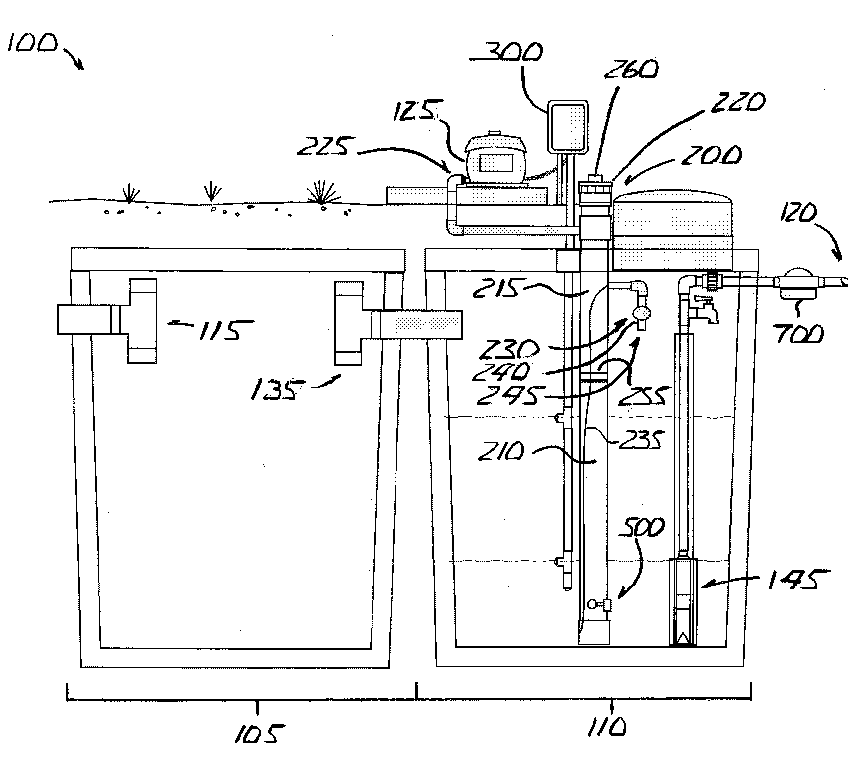
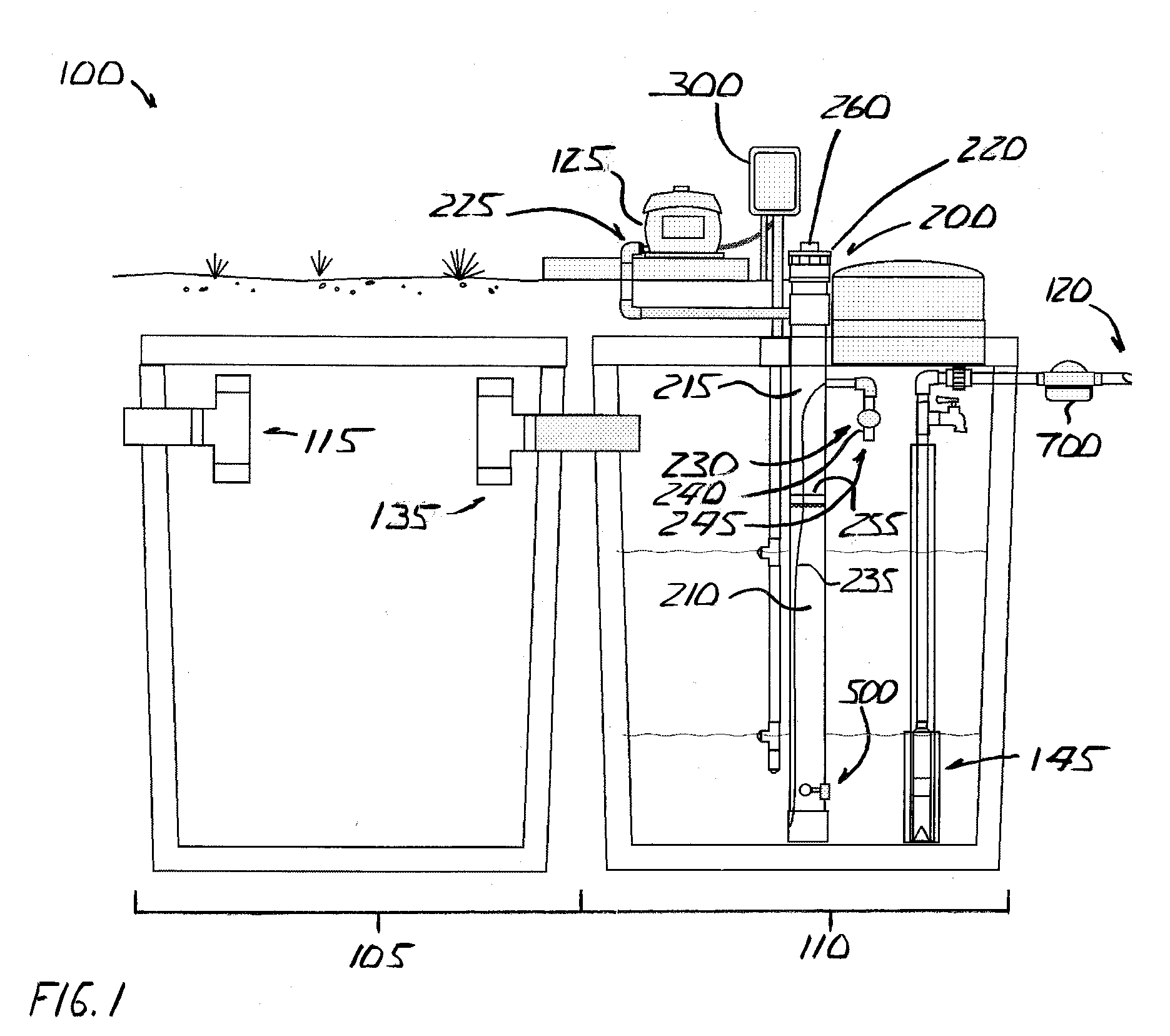
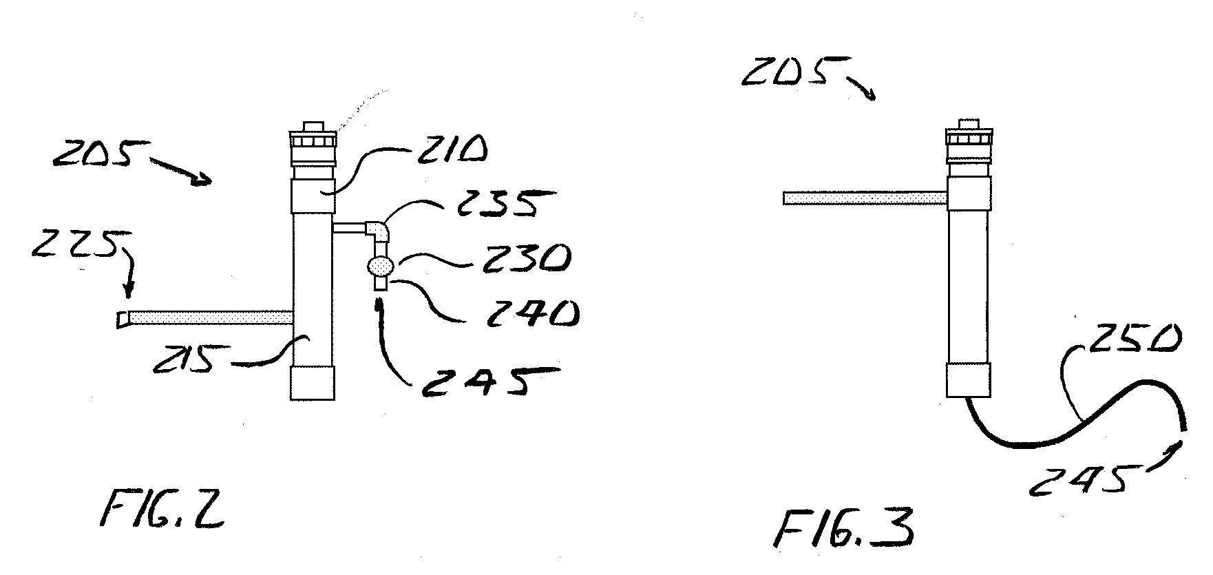
[0021]The invention is an apparatus for and method of dosing a wastewater treatment system, particularly suited for disinfection, that a wastewater treatment system fluid source or pump, such as an air compressor, drives according to a sensed need.

[0022]Referring to FIG. 1, a conventional wastewater treatment system 100 includes at least a first chamber 105 for receiving and treating raw effluent and a second chamber 110 for receiving treated effluent for subsequent return to the environment. Raw effluent enters first chamber 105 via an inlet 115, and exits second chamber 110 via outlet 120.

[0023]Wastewater treatment system 100 includes a fluid source 125 for delivering a fluid, such as air, for example, for aerobic decomposition of wastewater therein. For example, fluid source 125 may supply diffusers (not shown) that bubble small air bubbles up from the bottom of first chamber 105.

[0024]Effluent entering chamber 105 hydrodynamically urges or displaces effluent already in chamber 1...


PUM

PropertyMeasurementUnit
pressureaaaaaaaaaa
pressureaaaaaaaaaa
voidingaaaaaaaaaa

Abstract

A reservoir is configured to receive a first fluid, and has an inlet configured to receive a second fluid and an outlet. Second fluid received in the reservoir drives a corresponding amount of first fluid out of the outlet and into the wastewater treatment system. A method also is disclosed.

Description

BACKGROUND OF THE INVENTION[0001]Wastewater treatment plants typically include a pump tank that stores treated effluent until some triggering event occurs, and then the treated effluent is pumped to ground. The treated effluent from a pump tank may be connected to a sprinkler system and used to water a garden or lawn proximate to the wastewater treatment plant.[0002]Unfortunately, the aerobic and anaerobic processes involved in breaking down the effluent do not reduce pathogens that, if discharged, could cause great harm to the nearby living organisms. Accordingly, most wastewater treatment plants provide for disinfecting the treated effluent prior to discharge.[0003]Water and wastewater treatment processes typically conclude by disinfecting with a disinfectant or biocidal agent, such as bromine or chlorine. Chlorine is the most common water and wastewater agent used throughout the world today.[0004]A variety of techniques are known or used for introducing these and other agents int...

Claims


Application Information

Patent Timeline
Patent Type & Authority Applications(United States)
IPC IPC(8): C02F1/00
CPCC02F1/686C02F1/76C02F2303/04C02F2209/40C02F2209/42C02F2209/005
Inventor CORMIER, MURPHY J.CORMIER, TROY L.SUCHECKI, RONALD J.PERTUIT, ROBERT K.BROWN, DONALD L.
Owner HOOT AEROBIC SYST
Why Eureka
Try Eureka