
Fan for air conditioner

a technology for air conditioners and fans, applied in the direction of piston pumps, heating types, magnetic circuit shapes/forms/construction, etc., can solve the problems of low overall efficiency, low heat exchange efficiency, and low overall efficiency above 40 50%, so as to enhance the efficiency of the fan and reduce noise. , the effect of heat exchange efficiency

Inactive Publication Date: 2008-04-10
LG ELECTRONICS INC
View PDF65 Cites 25 Cited by
  • Summary
  • Abstract
  • Description
  • Claims
  • Application Information

AI Technical Summary

Benefits of technology

[0012]An object of the present invention is to provide a fan apparatus for an air conditioner which can reduce noise, and enhance a fan efficiency, and a heat exchange efficiency by employing a BLDC motor that can make stable drive of the fan, and increase an air flow rate.
[0013]The object of the present invention can be achieved by providing a fan apparatus for an air conditioner including a fan, a shaft coupled to the fan, a rotor for transmission of driving force to the shaft for rotating the fan, a stator on an inside of the rotor to form a BLDC motor together with the rotor, and a fan housing for enclosing the fan, thereby reducing noise and enhancing fan efficiency.

Problems solved by technology

In the meantime, the foregoing outdoor unit of the related art air conditioner has a limited installation place due to high concentration of a city, with consequential strengthening of environmental control, and becomes an object of complaints due to noise and heat emission.
However, the air conditioner outdoor units of a front suction / discharge type has low fan, and heat exchange efficiencies due to a smaller air suction area than the air conditioner outdoor unit of three side suction / discharge type.
Moreover, the general single phase or three phase induction motor used for the fan of the air conditioner outdoor unit of the front suction / discharge type has problems in that an overall efficiency is low below 40˜50%, and rotation speed variation is limited to a small range due to a narrow stable torque range.
If a rotation speed is outside of the stable torque range, noise becomes heavier and efficiency becomes poorer.

Method used


Image

  • Fan for air conditioner
  • Fan for air conditioner
  • Fan for air conditioner

Examples


Embodiment Construction

[0043]Reference will now be made in detail to the preferred embodiments of the present invention, examples of which are illustrated in the accompanying drawings. In describing the embodiments, identical parts will be given to the same names, and additional and repetitive description of which will be omitted.

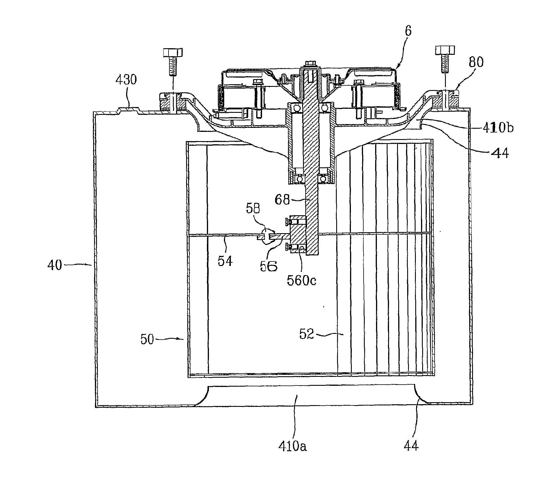
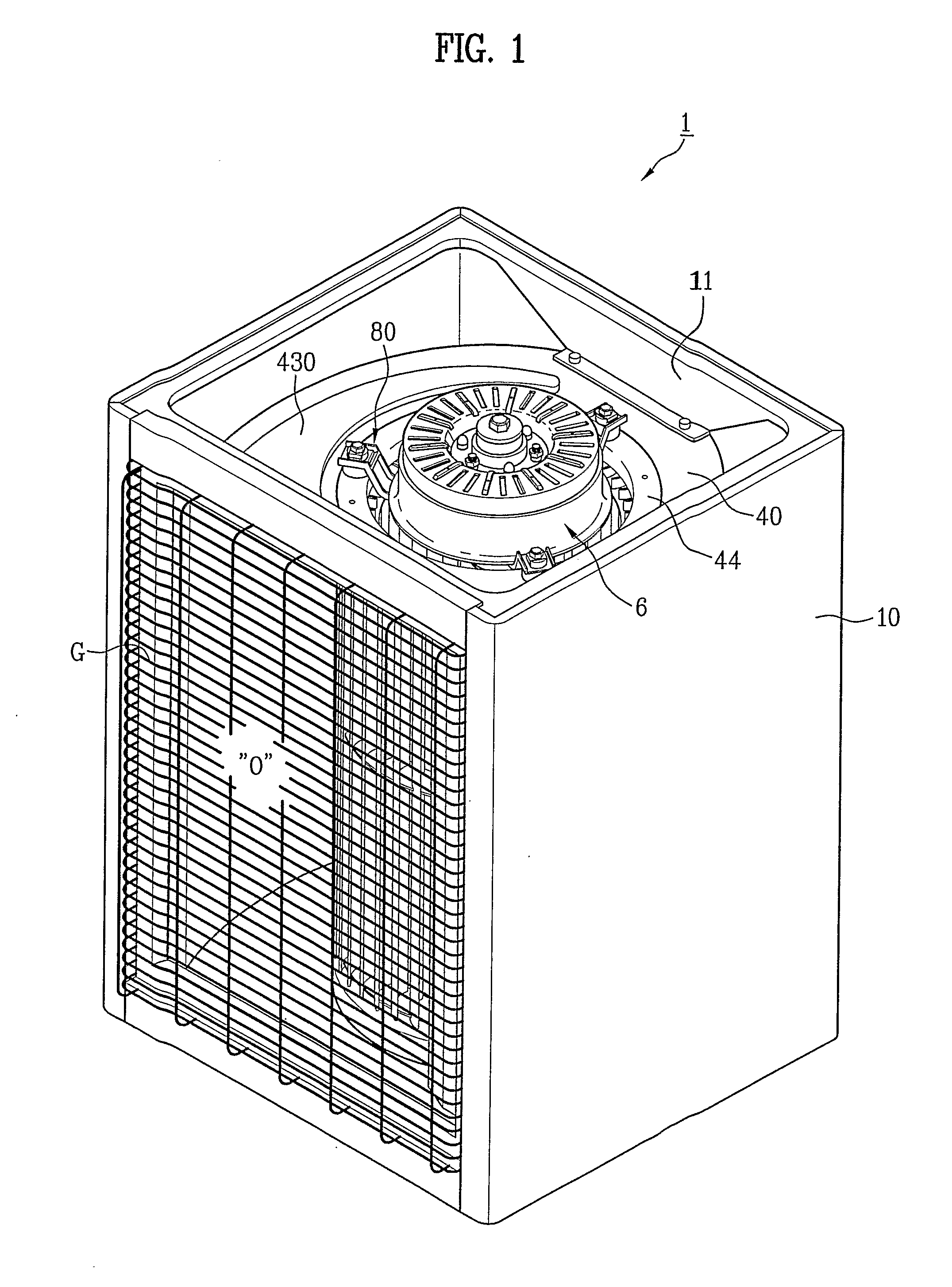
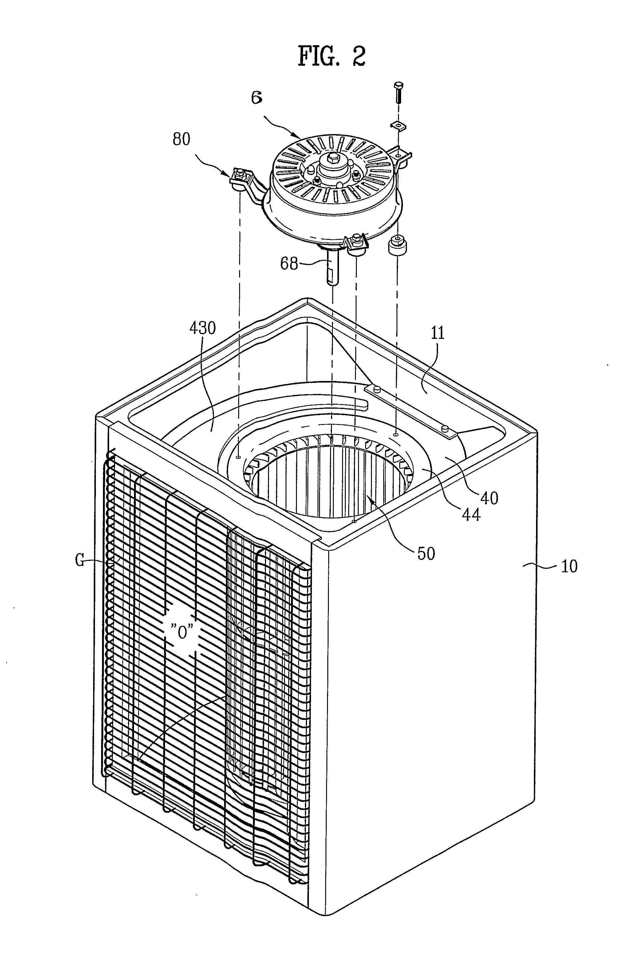
[0044]FIG. 1 illustrates a perspective view of a fan apparatus for an air conditioner in accordance with a preferred embodiment of the present invention, FIG. 2 illustrates a reference perspective view of an assembly of a BLDC motor and a supporter in a state the assembly is separated from a fan housing and a fan, FIG. 3A illustrates a section of a fan apparatus in accordance with a preferred embodiment of the present invention, and FIG. 3B illustrates a partial enlarged view of the motor and the supporter in FIG. 3A.

[0045]Though the fan in FIG. 3A shows a half section, with a bushing therein shown only a half accordingly, the bushing has a disc shape with symmetric left and righ...


PUM


Abstract

Fan apparatus for an air conditioner including a fan (50), a shaft (68) coupled to the fan (50), a rotor (60) for transmission of driving force to the shaft (68) for rotating the fan (50), a stator (65) on an inside of the rotor (60) to form a BLDC motor together with the rotor (60), and a fan housing (40) for enclosing the fan (50), thereby reducing noise and enhancing fan (50) efficiency.

Description

TECHNICAL FIELD[0001]The present invention relates to fan apparatuses for air conditioner, and more particularly, to a fan apparatus having a stable and high efficiency BLDC motor employed therein for enhancing fan, and heat exchange efficiencies.BACKGROUND ART[0002]In general, in the air conditioners, there are split type air conditioners each having an indoor unit and an outdoor unit respectively installed in a room space and an outdoor separately, and unit type air conditioners each having an indoor unit and an outdoor unit fabricated as one unit, for installation on a window or wall, wherein the split type air conditioners are used widely because, not only of sizes of the indoor units and the outdoor units that become the larger as cooling / heating capacities of the air conditioners become the larger, but also of heavy vibration of the outdoor units coming from compressors therein.[0003]The split type air conditioner is provided with the indoor unit in a room to make heat exchang...

Claims


Application Information

Patent Timeline
IPC IPC(8): H02K9/06H02K7/00F04B17/00F24F5/00F04D25/06F04D29/66F24F1/0325H02K3/52H02K7/14
CPCF04D29/668F24F1/0007H02K3/522F04D25/0646F24F1/0018F24F1/0022F04D25/064H02K7/14F04D25/082F24F1/0325F04D29/5806F24F5/00
Inventor KIM, IN GYU
Owner LG ELECTRONICS INC
Learn More