Ophthalmic system and method

Inactive Publication Date: 2008-04-10
BAUSCH & LOMB INC
View PDF28 Cites 24 Cited by
  • Summary
  • Abstract
  • Description
  • Claims
  • Application Information

AI Technical Summary

Benefits of technology

[0016]In more exemplary terms, embodiments of the invention provide an apparatus and method that are used to generate a diagnostic wavefront probe beam using optical imaging to control probe beam spot shape and size on the cornea and retina of a subject's eye. A rotating, scanning or otherwise moving holographic diffuser can be used in a laser beam path to generate a diffused light source that eliminates an over-tightly focused spot on the retina. Scanning or rotating the diffuser randomizes the relative phase across the beam to minimize speckle in the Hartmann-Shack aerial images. First and second pinhole apertures are prov

Problems solved by technology

However, a coherent light beam may produce an over-tight focal spot on retina.
An over-tight focal spot on retina limits the light power that can safely be injected into the eye.
The temporal coherence of the beam also produces beam speckle, which degrades the quality of the Hartmann-Shack aerial images.
While these approaches may be relatively effective for beam size confinement and focusing considerations, they do not address the speckle issue.
A further limitation with

Method used


Image

  • Ophthalmic system and method
  • Ophthalmic system and method
  • Ophthalmic system and method

Examples


Embodiment Construction

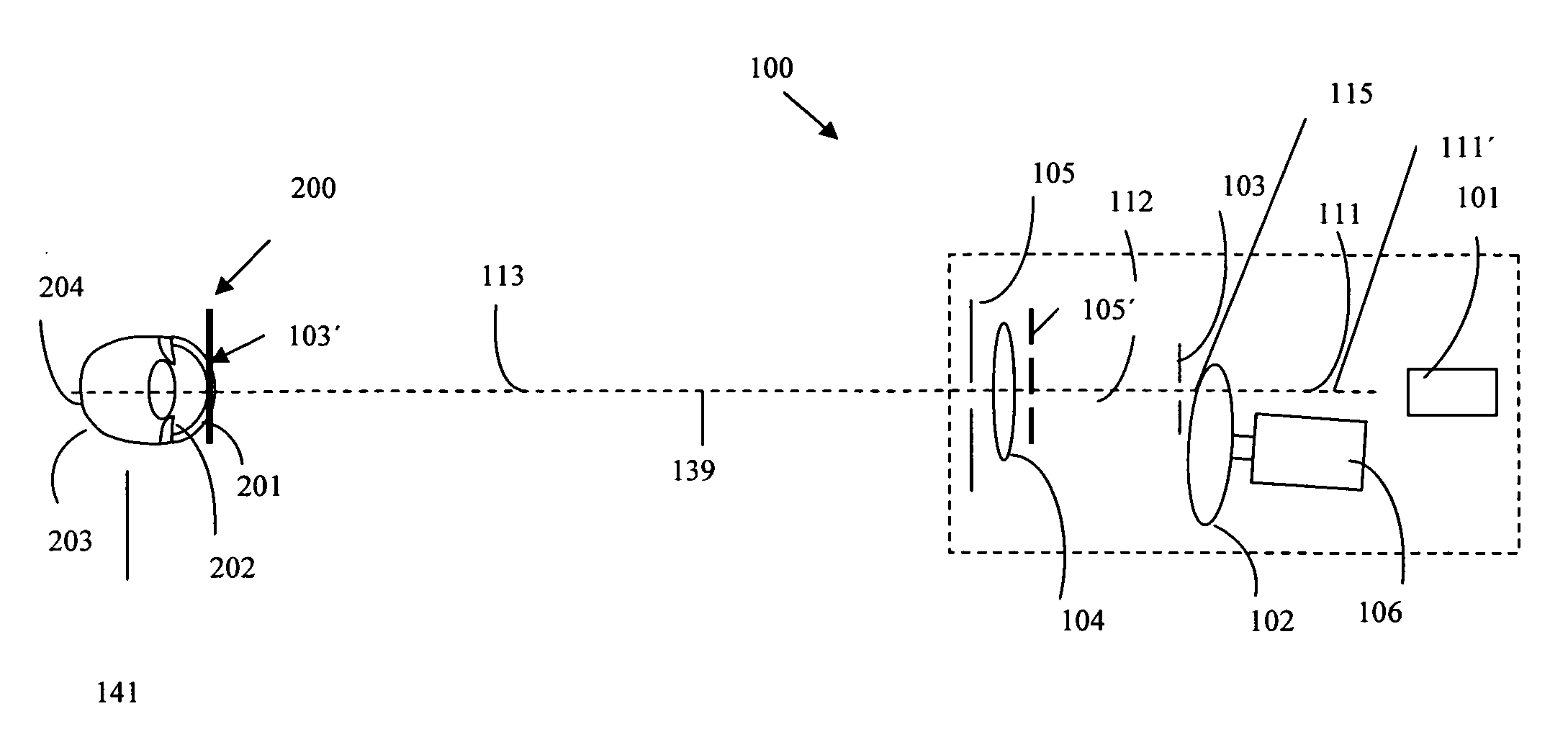
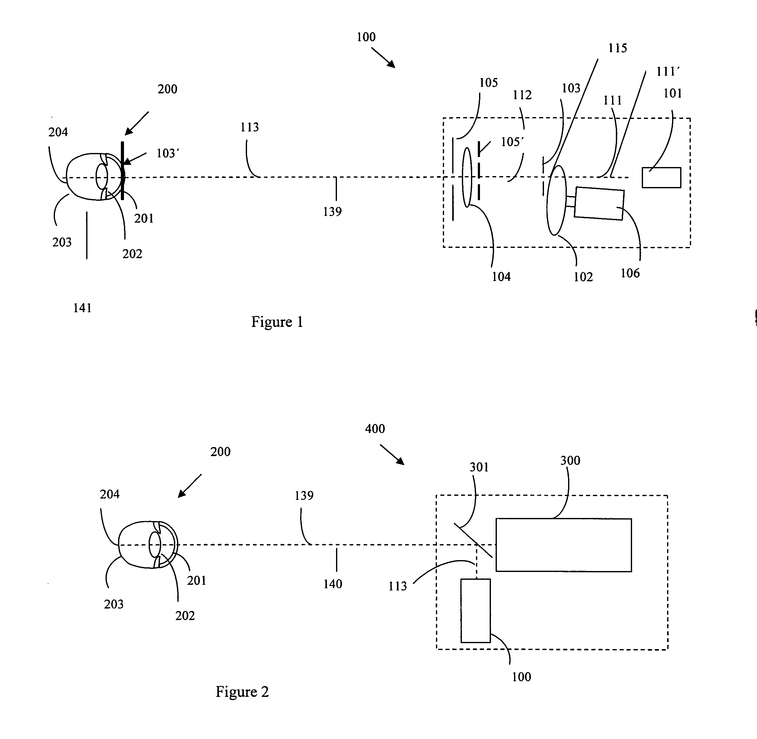
[0021]FIG. 1 is a schematic diagram of an exemplary ophthalmic system 100 that is particularly suited for generating a probe beam 113 used in diagnostic measurement of a subject's eye 200. The system 100 includes a light source 101 that produces at least a semi-coherent light beam 111 along a source light path 111′. A diffuser 102 is disposed in the source light path 111′ that produces a diffused light output 115 from the light beam 111. A first pinhole aperture 103 is disposed along an optical (eye) / instrument axis 139 in the path of the diffused light output 115. An optical component 104 is disposed along the optical axis 139. The optical component 104 forms a probe beam 113 of the diffused light output 115, as well as a first image 103′ of the first pinhole aperture 103 at a first predetermined image plane location 201. A second pinhole aperture 105 is disposed along the optical axis 139 between the optical component 104 and the first predetermined image plane location 201 and is...


PUM


Abstract

Ophthalmic system and method particularly suited to providing a laser probe beam for a Hartmann-Shack ophthalmic aberrometer. The laser probe beam produced by the system and method has a confined image spot at both the cornea and the retina. The probe beam can be generated with a laser beam passing through a moving holographic diffuser and two pinhole apertures. The holographic diffuser randomizes the spatial phase across the laser probe beam to substantially eliminate laser speckle from the Hartmann-Shack images. An imaging lens forms the probe beam and a first pinhole aperture image on the cornea, which eliminates beam size variation due to laser parameters and misalignment. A second-pinhole aperture is used to control the vergence of the probe beam and the probe beam spot size on the retina. The spot size on the retina is thus insensitive to the defocus power range of various subjects' eyes. The confined image spot on the retina substantially eliminates the possibility of an over-tight laser focal spot and allows the injection of higher laser power into the eye.

Description

BACKGROUND OF THE INVENTION[0001]1. Field of the Invention[0002]Embodiments of the invention generally relate to an ophthalmic system and method. More particularly, embodiments of the invention are directed to an ophthalmic system that provides a probe beam for optical diagnostic measurements and an ophthalmic method for generating a probe beam for optical diagnostic measurements. Embodiments of the invention are most particularly directed to apparatus and methods for making diagnostic ophthalmic wavefront measurements.[0003]2. Description of Related Art[0004]Ophthalmic wavefront sensors have been widely used to objectively measure higher-order aberrations of a subject's eye. The wavefront measurements are often used to provide data for customized photo-refractive surgery or other ophthalmic diagnostic and therapeutic procedures. Various types of wavefront sensors are known in the art. One of the most common types of ophthalmic wavefront sensors is the Hartmann-Shack system. In a Ha...

Claims


Application Information

Patent Timeline
IPC IPC(8): A61B3/10
CPCA61B3/15A61B3/0008
Inventor LAI, MINGEAGAN, BARRY T.STACK, CASEYBENTLEY, JOSEPHWANG, DAOZHI
Owner BAUSCH & LOMB INC
Why Eureka
Try Eureka