Ultrasound diagnosis apparatus

a technology of ultrasound and diagnostic equipment, applied in the field of ultrasound diagnosis equipment, can solve the problems of insufficient quantitative evaluation precision, difficult quantitative diagnosis of the degree of joining, treatment to which these methods can be applied, etc., and achieve the effect of influencing individual differences due to a difference in form

Active Publication Date: 2008-04-10
HITACHI LTD
View PDF7 Cites 8 Cited by
  • Summary
  • Abstract
  • Description
  • Claims
  • Application Information

AI Technical Summary

Benefits of technology

[0010] According to one aspect of the present invention, there is provided an ultrasound diagnosis apparatus comprising a transmission and reception unit which forms a plurality of ultrasonic beams on a target bone, a surface point identifying unit which identifies a surface point corresponding to a surface of the target bone for each ultrasonic beam, an angle calculating unit which calculates a bending angle of the target bone based on a plurality of surface points, and a characteristic information generator unit which generates characteristic information which reflects a mechanical characteristic of the target bone based on a bending angle of the target bone due to an external action and form data which is unique to the target bone.
[0011] With the above-described structure, a bone can be evaluated in consideration of form data which is unique to the target bone. Because of this, for example, bone can be evaluated while influences of indivi

Problems solved by technology

However, because an image of a callus which is growing in the diseased area cannot be clearly captured with X-ray photography, quantitatively diagnosing the degree of joining remains difficult.
These methods, however, have var

Method used


Image

  • Ultrasound diagnosis apparatus
  • Ultrasound diagnosis apparatus
  • Ultrasound diagnosis apparatus

Examples


Embodiment Construction

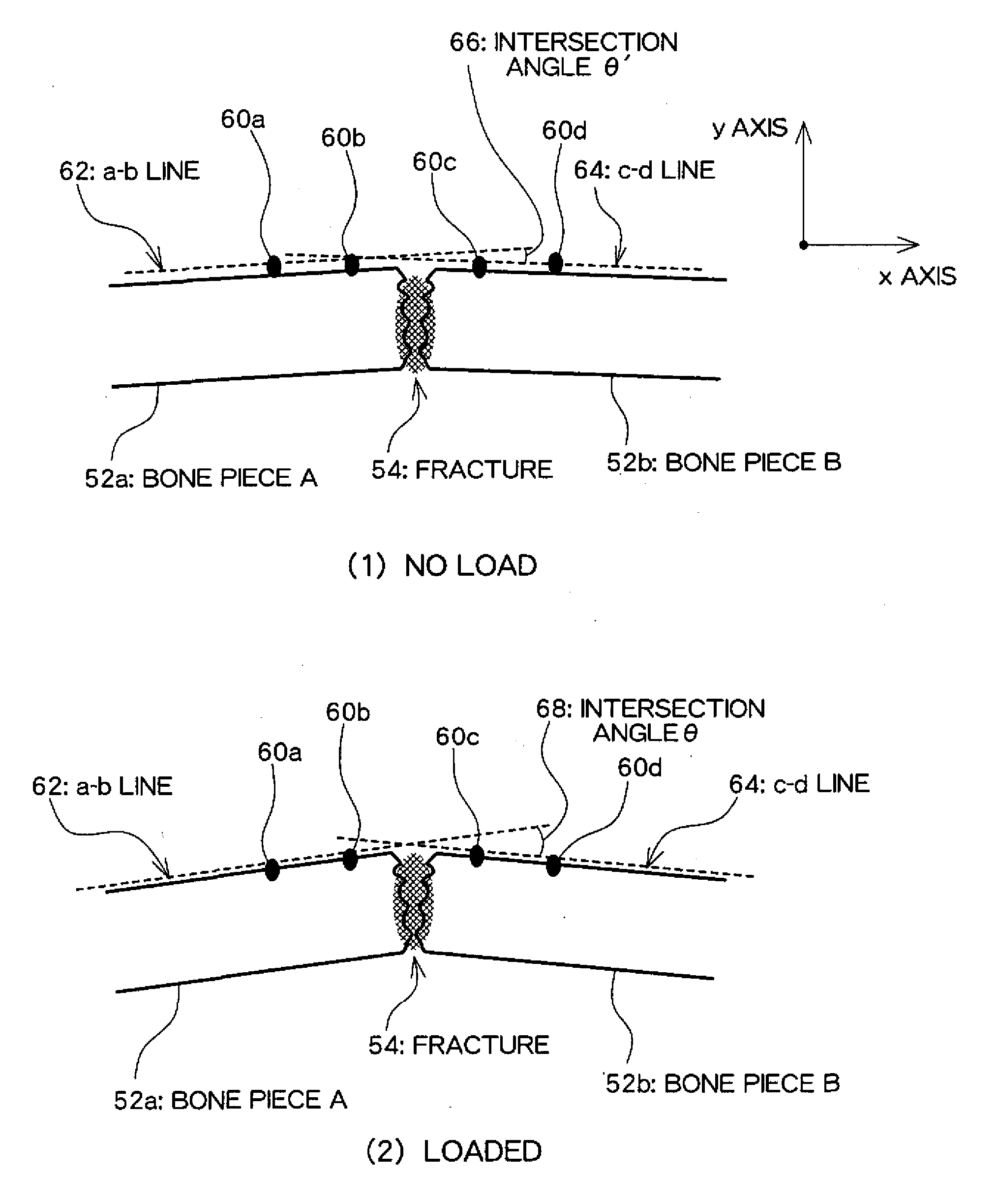
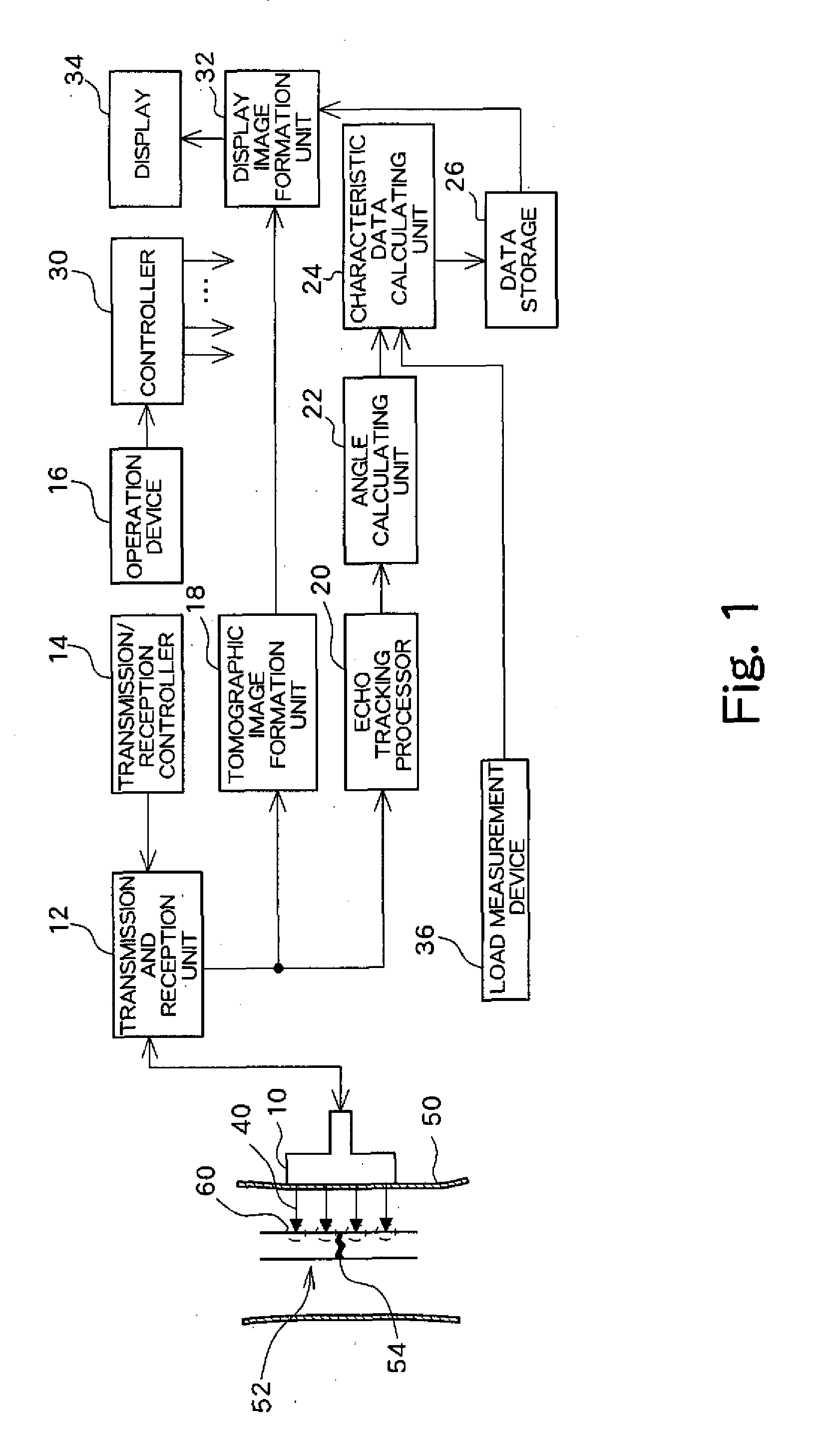
[0025]FIG. 1 illustrates a preferred embodiment of an ultrasound diagnostic apparatus according to the present invention. FIG. 1 is a block diagram showing an overall structure of the ultrasound diagnostic apparatus. A probe 10 is an ultrasonic probe which is used in contact with a surface of the body of a subject 50. The probe 10 forms a plurality of ultrasonic beams 40 directed towards a bone 52 within the body of the subject 50. In this process, for example, a plurality of ultrasonic beams 40 are formed on each of two upper and lower bone pieces sandwiching a fractured part 54 of the bone 52. Surface points 60 which are set on a surface of the bone 52 will be described later in more detail.

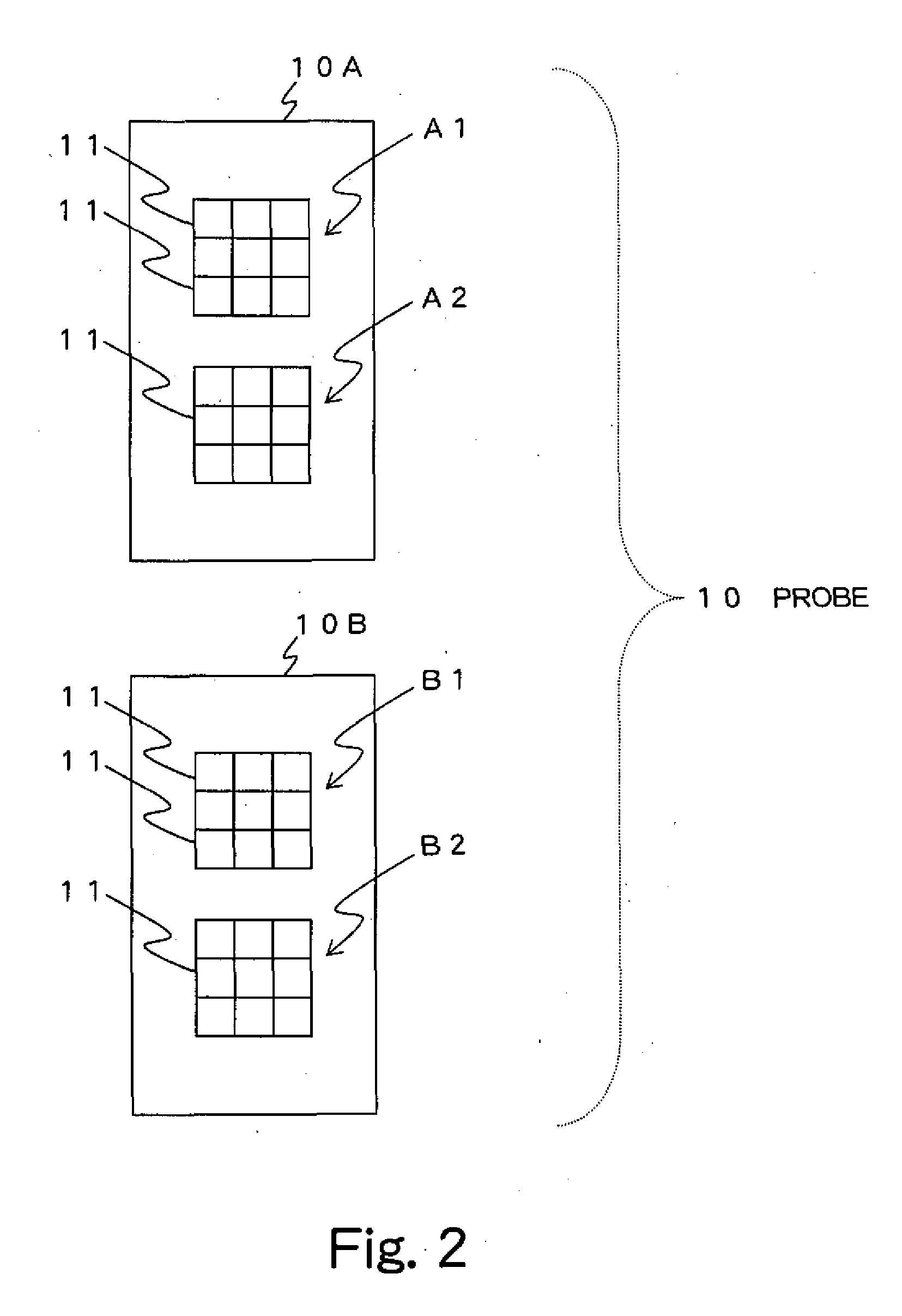
[0026]FIG. 2 is a diagram for explaining a probe 10 which may be preferably employed with the ultrasound diagnosis apparatus of the present embodiment. The probe 10 comprises a probe pair including a probe 10A and a probe 10B. The probe 10A comprises, within the probe 10A, a subarray A1 and a ...


PUM


Abstract

An angle calculating unit calculates a bending angle of a bone based on a plurality of surface points. A characteristic data calculating unit determines an indication value which reflects a load applied on the bone, a bone length of the bone, and a position of a fractured part. The characteristic data calculating unit calculates, as characteristic data reflecting a mechanical characteristic of the bone, a proportionality constant indicating a ratio between the indication value and the bending angle of the bone.

Description

BACKGROUND [0001] 1. Technical Field [0002] The present invention relates to a technique for evaluating bone using ultrasound. [0003] 2. Description of the Related Art [0004] An easy means for quantitative measurement of mechanical characteristics of bone is desired for evaluating, for example, the state of joining of a bone fracture. In related art, X-ray photography is widely used for evaluating the state of a bone fracture. However, because an image of a callus which is growing in the diseased area cannot be clearly captured with X-ray photography, quantitatively diagnosing the degree of joining remains difficult. The measurement of mechanical characteristics of bone is not limited to a fractured bone, and may be executed on healthy bone tissue. For example, a measurement of the bone strength or the like of a healthy bone can be useful in the diagnosis of osteoporosis or the like. [0005] There are known methods for quantitatively evaluating mechanical characteristics of bone with...

Claims


Application Information

Patent Timeline
IPC IPC(8): A61B8/00
CPCA61B8/485A61B8/0875
Inventor SAKAI, RYOICHIHARADA, AKIMITSU
Owner HITACHI LTD
Why Eureka
Try Eureka