
Fiber reinforced resin polymer mortar pole

Active Publication Date: 2008-04-17
NOV NORTH AMERICA I P LLC
View PDF19 Cites 19 Cited by
  • Summary
  • Abstract
  • Description
  • Claims
  • Application Information

AI Technical Summary

Benefits of technology

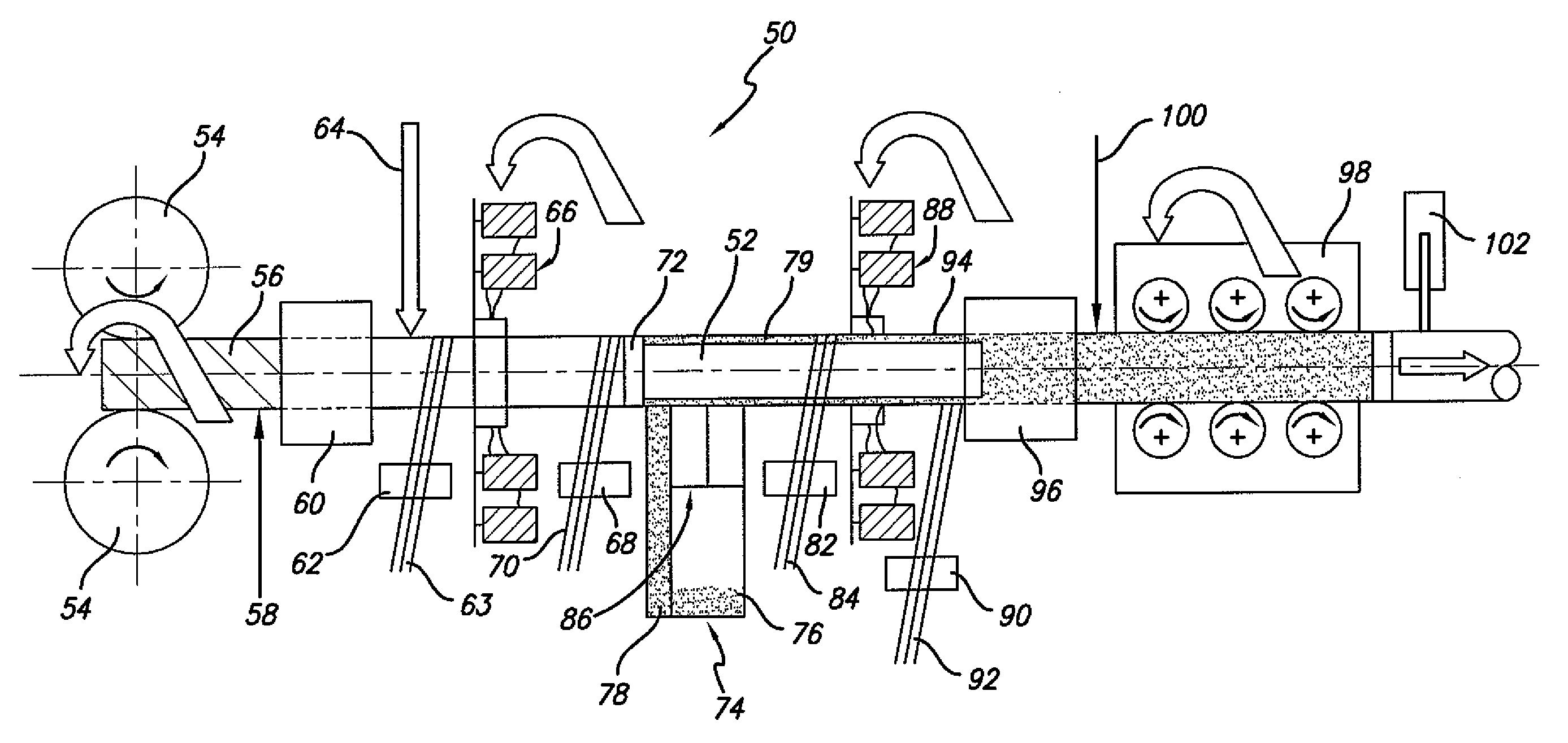
[0014]Fiber reinforced resin poles of this invention are preferably formed using a continuous process on a rotating mandrel, making use of different sequentially position stations to form the different portions of the pole as the fabrication is being moved axially along the mandrel. Poles of this invention enable one to tailor the construction features in a manner calculated to realize optimal tensile and compressive strength for providing a desired resistance to bending stress or buckling for accommodating use with popular pole applications, e.g., for carrying utility or power lines or the like. Poles of this invention that are constructed using a continuous process that enables one to use different materials for making different portions of the pole, thereby introducing manufacturing flexibility into the fabrication process to assist in achieving a pole construction having the above-noted desired optimized properties.

Problems solved by technology

While the above example demonstrates that is it known to form a pole from fiberglass reinforced resin materials, the reliance on multiple layers of fiberglass reinforced resin material to build the wall thickness needed to provide a desired compressive strength and resistance to buckling results in the production of a pole that is relatively expensive compared to more traditional materials based on the raw material costs.
A composite pole manufactured as described above has the following structural issues: (1) the tensile strength of the longitudinally oriented fibers is very high and imparts the bulk of the strength in the tensile direction; (2) the longitudinally oriented fibers however do not have the same compressive strength as they do tensile strength.
(3) In designing for local wall buckling under compression (i.e., the full local wall thickness), the local wall may fail in buckling long before the compressive strength is reached.
Further, the process described above for making a single pole by the sequentially performed steps noted above including cutting and laying individual strips of the fiberglass reinforced resin material forming the intermediate and outer layers, is one that is time consuming and costly from a manufacturing perspective.

Method used


Image

  • Fiber reinforced resin polymer mortar pole
  • Fiber reinforced resin polymer mortar pole
  • Fiber reinforced resin polymer mortar pole

Examples


Embodiment Construction

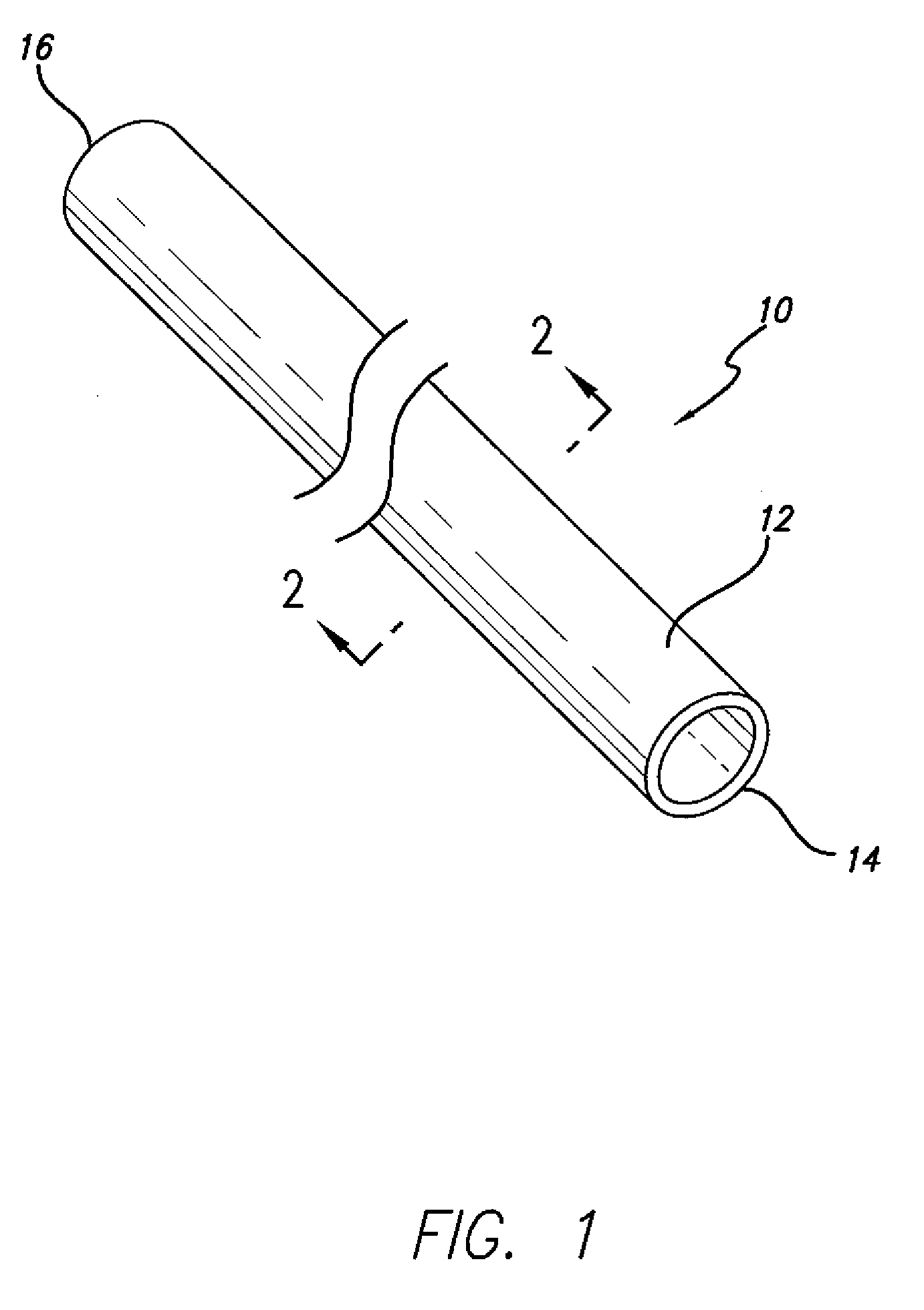
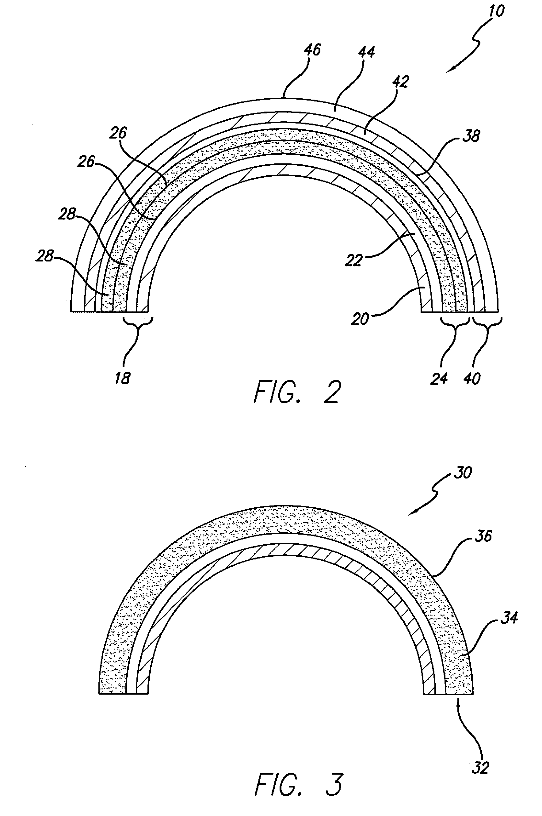
[0022]Fiber reinforced resin poles of this invention generally comprise a composite construction including a fiber reinforced resin structure including a plurality of axially-oriented fiber reinforced resin layers and one or more polymer mortar material layers, wherein such construction is specially engineered having combined properties of tensile strength and compression strength calculated to provide a desired axial tensile strength, axial compressive strength, and resistance to buckling to meet the particular end-use application conditions of the pole.

[0023]As explained in greater detail below, in an example embodiment, poles of this invention are preferably constructed using a continuous process, and the polymer mortar material is provided in the form of one or more layers within the pole to cost effectively provide a desired wall thickness to the pole structure to provide a desired compression strength. Further, poles of this invention use longitudinally- or axially-oriented fi...


PUM

PropertyMeasurementUnit
Fractionaaaaaaaaaa
Angleaaaaaaaaaa
Lengthaaaaaaaaaa

Abstract

Poles of this invention have an annular body with a wall structure comprising a number of fiber reinforced resin layers, which can be positioned to form an inside and / or outside portion of the wall structure. A portion of the layers are oriented longitudinally within the wall structure, and the wall structure also includes radially-oriented fiber reinforced resin layers. The pole includes one or more layers or a core of a composite material or polymer mortar disposed within one or more locations of the wall structure, e.g., as an intermediate layer and / or as part of the wall inside and / or outside portion. The pole can include an outside surface resistant to ultra violet radiation. Poles of this invention can be formed using a continuous process on a rotating mandrel, making use of differently positioned stations to form the different portions of the pole as the fabrication is moved axially along the mandrel.

Description

FIELD OF THE INVENTION[0001]This invention relates to poles used for a variety of applications such for carrying and supporting utility power lines or the like and, more particularly, to poles that are specially constructed from fiber reinforced resin having one or more polymer mortar layers for the purpose of providing a cost effective structure having optimized compressive and tensile strength for providing a resistance to bending stress well suited for use in conventional pole applications.BACKGROUND OF THE INVENTION[0002]The use of poles are well known for such applications as for carrying utility power lines and the like, for accommodating the placement of lights thereon, or for accommodating the placement of other devices thereon a desired distance from the ground. Such poles have been conventionally formed from solid wood, steel, aluminum, or concrete having a desired thickness or outside diameter, and have also been formed from metal having an inside and outside diameter des...

Claims


Application Information

Patent Timeline
IPC IPC(8): B29D22/00
CPCB29C53/60B29C53/8058B29C53/8075B29C70/205Y10T428/1393B29C70/50B29L2031/766E04H12/02B29C70/32B32B1/08B32B13/08
Inventor FRIEDRICH, RALPH S.ULRICH, RON G.DAVIDSON, JAMES W.MERCADO, HECTOR P.JONES, DAVID B.VIEGL, RONALD A.CHEN, LIMING
Owner NOV NORTH AMERICA I P LLC
Learn More