
Electrical receptacle and box apparatus

Inactive Publication Date: 2008-04-17
NICHOLSON ANDREW
View PDF22 Cites 5 Cited by
  • Summary
  • Abstract
  • Description
  • Claims
  • Application Information

AI Technical Summary

Benefits of technology

[0008]In accordance with the present invention, an improvement on existing electrical receptacles and junction boxes is disclosed, which is safer, easier to install and replace, and more cost effective to manufacture without compromising quality.

Problems solved by technology

The problems related to wiring electrical receptacles, including wall outlets, switches, and similar applications have been well documented.
Aside from the costs associated with new construction involving the costs of an electrician and a drywall or plaster technician, there are certain difficulties associated with the repair and replacement of electrical receptacles and occasionally junction boxes.
Replacement requires that the wires be reshaped and reattached to the new receptacle and then squeezed back into the junction box with the chance that one of the wires might break from being bent too much.
In the event that a junction box must be replaced, this usually means breaking a part of the sheetrock or drywall for access to the box, detaching the wires from the receptacle, pulling the wires out of the junction box, installing a new box, reshaping and sneaking the wires into the new box, reshape the wires again onto the receptacle and squeezing them in place, also with the chance of breakage.

Method used


Image

  • Electrical receptacle and box apparatus
  • Electrical receptacle and box apparatus
  • Electrical receptacle and box apparatus

Examples


Embodiment Construction

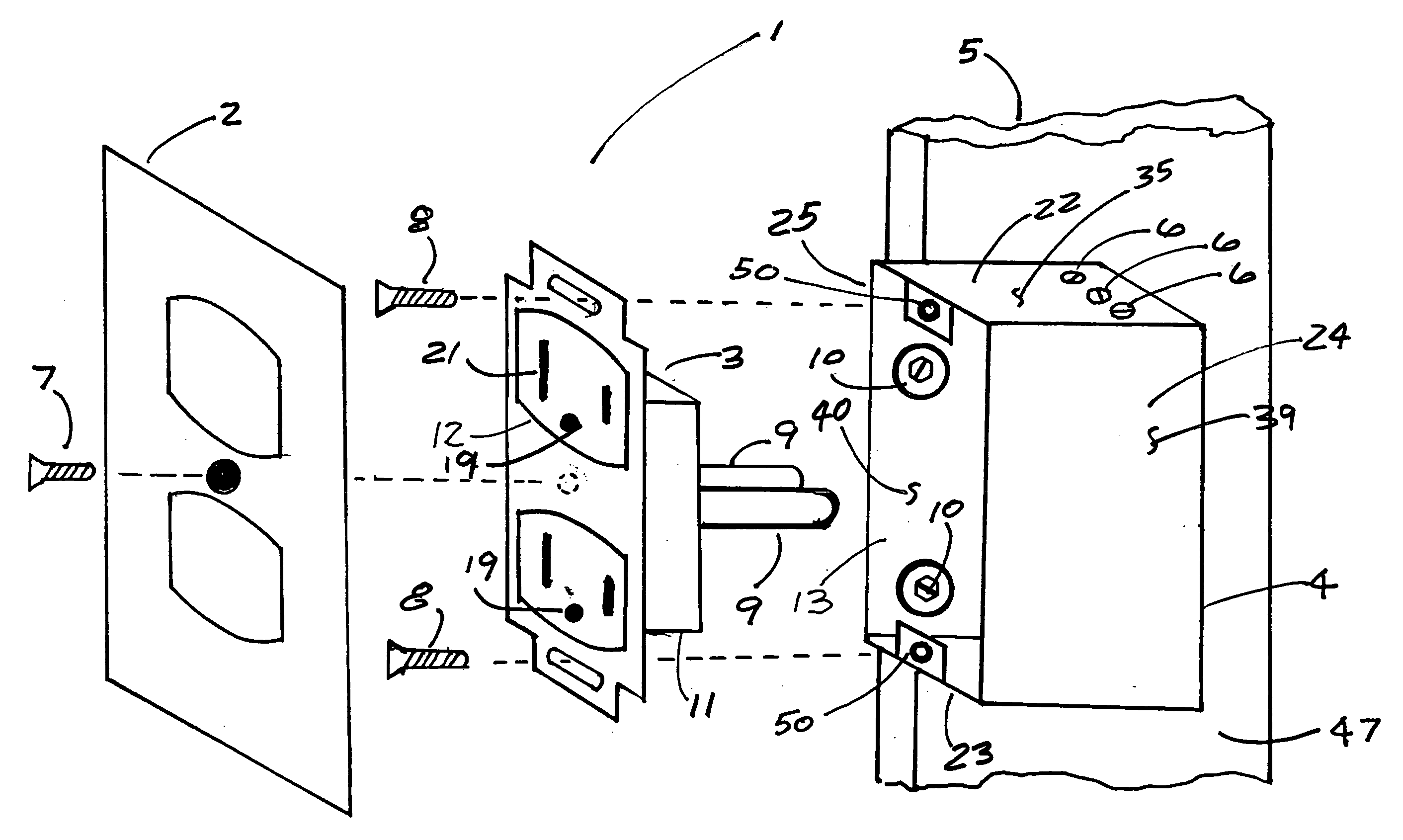
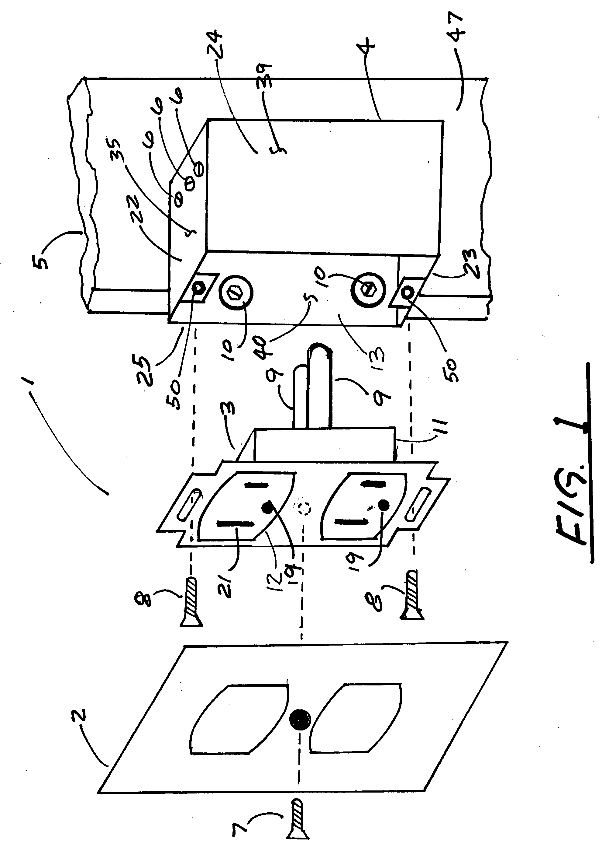
[0025]FIG. 1 depicts an exploded view of the inventive electrical receptacle and junction box apparatus 1 showing a slide-in receptacle 3 in position for insertion or removal from a junction box 4 fixedly attached to a building stud 5 by means of two stud attaching screws 10. Receptacle screws 8 hold the slide-in receptacle 3 in place in the junction box 4. The receptacle screws 8 attach to ground strip tabs 50 as more fully shown in FIG. 6. A typical faceplate 2 covers the slide-in receptacle 3 and is held in place by a faceplate screw 7.

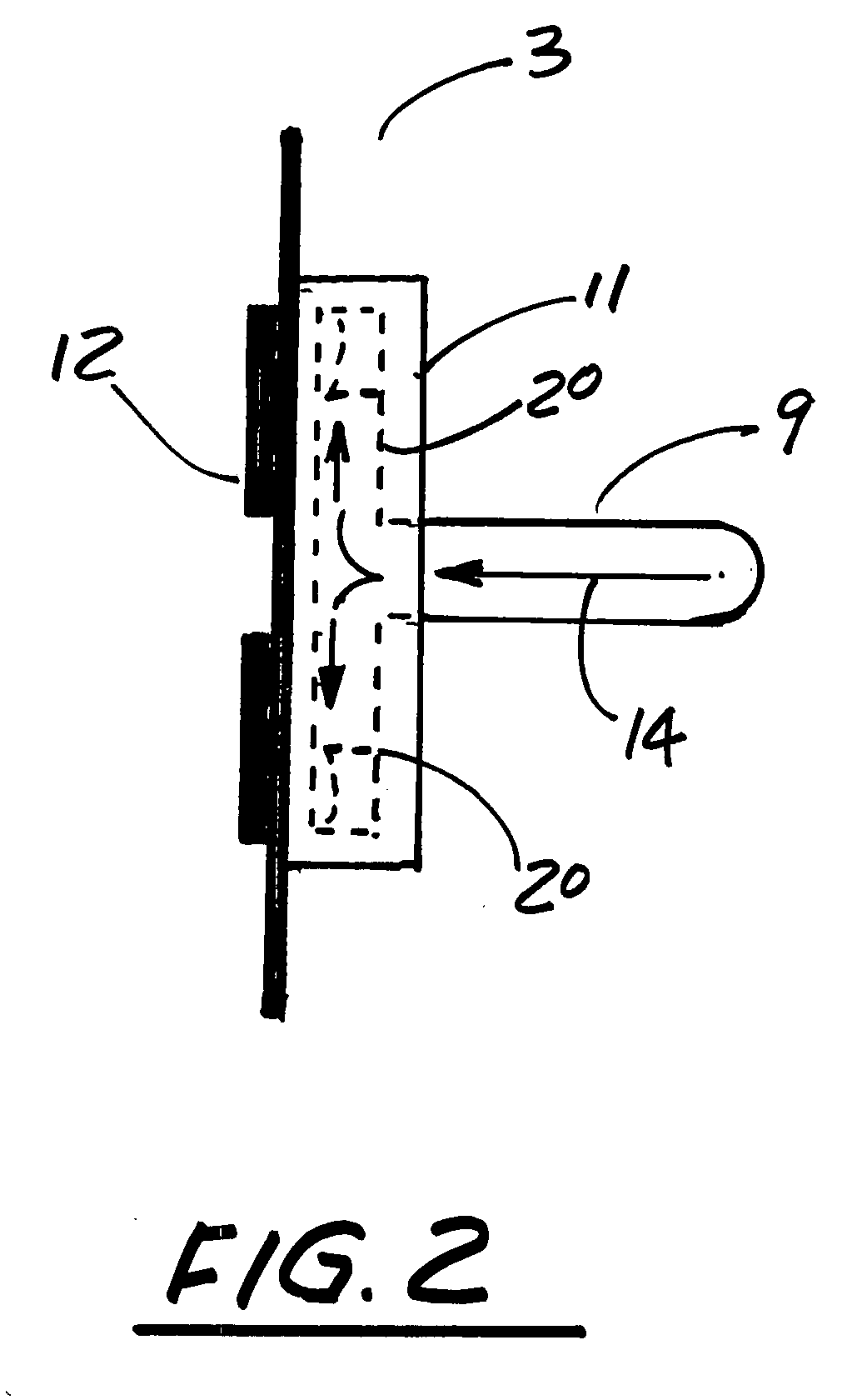
[0026]The slide-in receptacle 3 has a typical socket face 12 with electrical plug apertures 21 and ground plug openings 19. Also shown is a non-conductive electrical base 11 with rearward extending elongated prongs 9. While a slide-in receptacle 3 is shown, it is intended that other devices normally installed in wall junction boxes such as light switches and dimmers could be similarly adapted and fitted with a non-conductive electrical base 11 with...


PUM


Abstract

An electrical receptacle and junction box apparatus including a stud mounted electrical junction box with stud-attaching screw shoulders having wire apertures with retaining screws and retaining screw fittings for each wire aperture for receiving electrical wiring without wrapping the wiring around screws, a ground strip, a slide-in receptacle or slide-in switch received in the electrical junction box, an electrical connection between the electrical junction box and the slide-in receptacle or slide-in switch unit with elongated prongs, slotted terminals with slot apertures to allow the slide-in receptacle or slide-in switch to move in and out of the electrical junction box and non-conductive bases for embedding the terminals, the ground strip and the retaining screw fittings.

Description

[0001]This application claims priority from U.S. Provisional Application Ser. No. 60 / 829,053 (“the '053 application”) filed Oct. 11, 2006. The '053 application is incorporated here by reference.BACKGROUND OF THE INVENTION[0002]The present invention relates generally to electrical wiring systems and devices; and more particularly to an improved wireless electrical receptacle and electrical junction box apparatus which is safer, easier to install and replace and more cost effective and efficient to manufacture than conventional wired electrical receptacles.[0003]The problems related to wiring electrical receptacles, including wall outlets, switches, and similar applications have been well documented. Aside from the costs associated with new construction involving the costs of an electrician and a drywall or plaster technician, there are certain difficulties associated with the repair and replacement of electrical receptacles and occasionally junction boxes.[0004]Replacement of a conve...

Claims


Application Information

Patent Timeline
IPC IPC(8): H02G3/08H01R13/46
CPCH02G3/18H01R31/06
Inventor NICHOLSON, ANDREW
Owner NICHOLSON ANDREW
Features
  • Generate Ideas
  • Intellectual Property
  • Life Sciences
  • Materials
  • Tech Scout
  • Unparalleled Data Quality
  • Higher Quality Content
  • 60% Fewer Hallucinations
Learn More