Constant On-Time Regulator With Increased Maximum Duty Cycle

a technology of regulator and maximum duty cycle, which is applied in the direction of dc-dc conversion, power conversion system, instruments, etc., can solve the problems of unsatisfactory output signal noise and load voltage limit, ripple-mode regulation is more difficult, and the comparator voltage differential is not desirabl

Active Publication Date: 2008-04-17
MICREL
View PDF8 Cites 76 Cited by
  • Summary
  • Abstract
  • Description
  • Claims
  • Application Information

AI Technical Summary

Benefits of technology

[0015] According to one embodiment of the present invention, a buck switching regulator is formed on an integrated circuit and receives an input voltage where the buck switching regulator controls a high-side switch and a low-side switch using a feedback control loop to drive a switch output node for generating a switching output voltage. The switch output node is coupled to an LC filter circuit external to the integrated circuit to generate a regulated output voltage having a substantially constant magnitude on an output node. The regulated output voltage is fed back to the buck switching regulator to a voltage divider for generating a feedback voltage on a feedback voltage node. The buck switching regulator includes an on-time control circuit for generating a first signal for controlling the high-side switch under a minimum on-time and variable off-time feedback control loop where the first signal turns off the high-side switch at the expiration of a first on-time duration or at the expiration of a maximum on-time. The first on-time duration is at least a minimum on-time and can be expanded up to a maximum on-time when the feedback voltage remains less than the reference voltage. The maximum on-time can be a first maximum on-time and a second, extended maximum on-time greater than the first maximum on-time. The second, extended maximum on-time is applied when a minimum off-time was used for the high-side switch during the previous switching cycle.

Problems solved by technology

For voltage regulators using ripple-mode control, while the output ripple is useful in output voltage regulation, it is undesirable in terms of output signal noise and load voltage limits.
Low ripple serves the interests of noise minimization and reduced load voltage variation, but makes ripple-mode regulation more difficult.
Low ripple magnitude reduces the comparator voltage differentials, making accurate and fast comparison very difficult.
While these solutions allow for the use of low ESR capacitors in ripple-mode voltage regulators, these solutions add complexity and cost to the voltage regulators.
The requirement of a minimum amount of ripple voltage at the output signal limits the application of fixed on-time voltage regulators to cases where ripples in the output voltage can be tolerated.
Also, zero ESR capacitors, such as ceramic capacitors, which are usually cheaper than tantalum capacitors having large ESR, cannot be used because a minimum amount of ESR is required for proper control loop operation.

Method used


Image

  • Constant On-Time Regulator With Increased Maximum Duty Cycle
  • Constant On-Time Regulator With Increased Maximum Duty Cycle
  • Constant On-Time Regulator With Increased Maximum Duty Cycle

Examples


Embodiment Construction

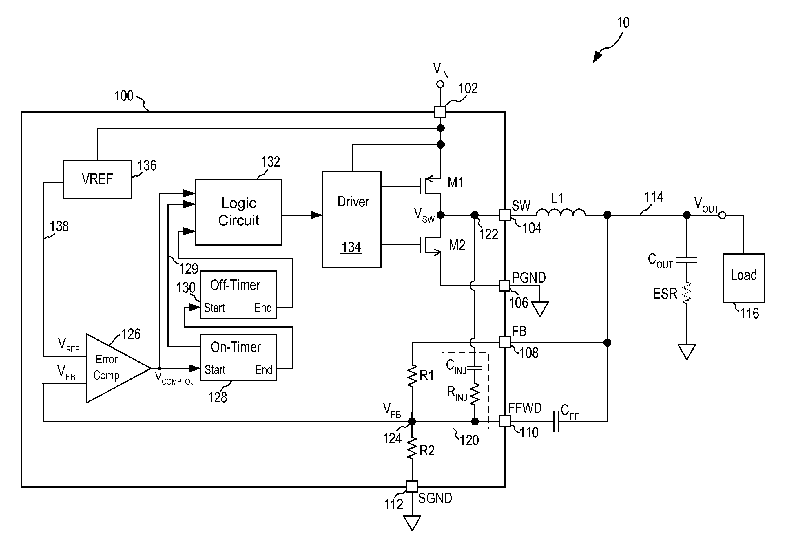
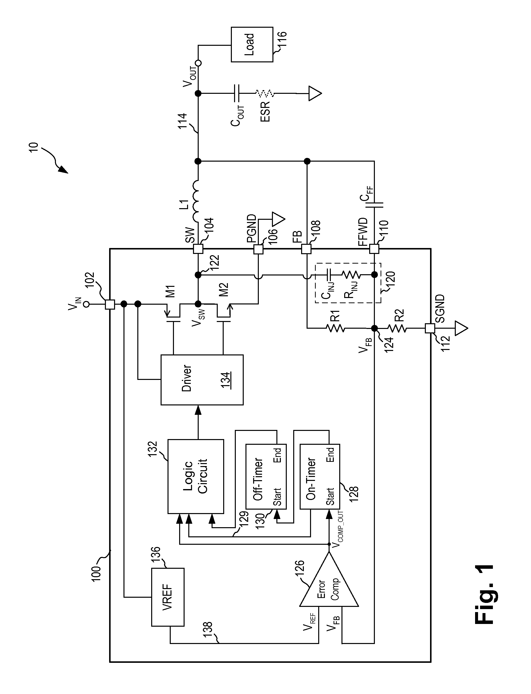
[0029] In accordance with the principles of the present invention, a buck switching regulator using a fixed on-time (or constant on-time) and minimum off-time control loop incorporates a ripple injection circuit for internally generating the necessary ripple using the switching output voltage and injecting the ripple voltage signal into the feedback control loop of the voltage regulator. The amount of ripple to be generated is adjusted by a feedforward capacitor which can be integrated onto the buck regulator or be externally coupled to the buck regulator. In this manner, the buck regulator can be configured to work with an output capacitor having any equivalent series resistors (ESR) values. In particular, when the output capacitor coupled to the buck regulator has a large ESR, the feedforward capacitor is used to program the ripple injection circuit to generate little or no ripple from the switching output voltage. However, when the output capacitor coupled to the buck regulator h...


PUM


Abstract

A buck switching regulator receives an input voltage and provides a switching output voltage on a switch output node using a minimum on-time, variable off-time feedback control loop. The buck switching regulator includes an on-time control circuit for generating a first signal for turning off the high-side switch at the expiration of a first on-time duration or at the expiration of a maximum on-time. The first on-time duration is at least a minimum on-time and is allowed to expand to a maximum on-time when the feedback voltage remains less than a reference voltage. The maximum on-time includes a first maximum on-time and a second, extended maximum on-time. The second maximum on-time is applied when a minimum off-time was used for the high-side switch during the previous switching cycle. In another embodiment, the second maximum on-time is applied only when the switching regulator is not being current limited.

Description

CROSS-REFERENCE TO RELATED APPLICATIONS [0001] This application is a continuation-in-part of application Ser. No. 11 / 530,548, filed Sep. 11, 2006, entitled “Ripple Generation In Buck Regulator Using Fixed On-Time Control To Enable The Use of Output Capacitor Having Any ESR” having at least one common inventor hereof, which application is incorporated herein by reference in its entirety. [0002] This application is related to concurrently filed and commonly assigned U.S. patent application Ser. No. ______, entitled “Constant On-Time Regulator With Internal Ripple Generation and Improved Output Voltage Accuracy,” of Ioan Stoichita, Matthew Weng and Charles Vinn, which application is incorporated herein by reference in its entirety.FIELD OF THE INVENTION [0003] The invention relates to switching regulators or DC-to-DC converters and, in particular, to a control scheme incorporated in a constant on-time buck regulator with multi-mode on and off time control. DESCRIPTION OF THE RELATED AR...

Claims


Application Information

Patent Timeline
Patent Type & Authority Applications(United States)
IPC IPC(8): G05F1/56
CPCH02M3/1563
Inventor WENG, MATTHEW
Owner MICREL
Why Eureka
Try Eureka