
Method and apparatus for manufacturing an auxiliary antenna

a technology of auxiliary antennas and manufacturing methods, applied in the direction of antennas, burglar alarms by hand-held items removal, etc., can solve the problems of not being able to be incorporated into the cardboard roll manufacturing process, too many manufacturing methods, and relatively slow and expensive application

Active Publication Date: 2008-04-17
HID TEXTILE SERVICES SARL
View PDF7 Cites 29 Cited by
  • Summary
  • Abstract
  • Description
  • Claims
  • Application Information

AI Technical Summary

Problems solved by technology

However, such manufacturing methods require too many steps and are relatively slow and expensive to apply.
They are also not able to be incorporated into a cardboard roll manufacturing process.

Method used


Image

  • Method and apparatus for manufacturing an auxiliary antenna
  • Method and apparatus for manufacturing an auxiliary antenna
  • Method and apparatus for manufacturing an auxiliary antenna

Examples


Embodiment Construction

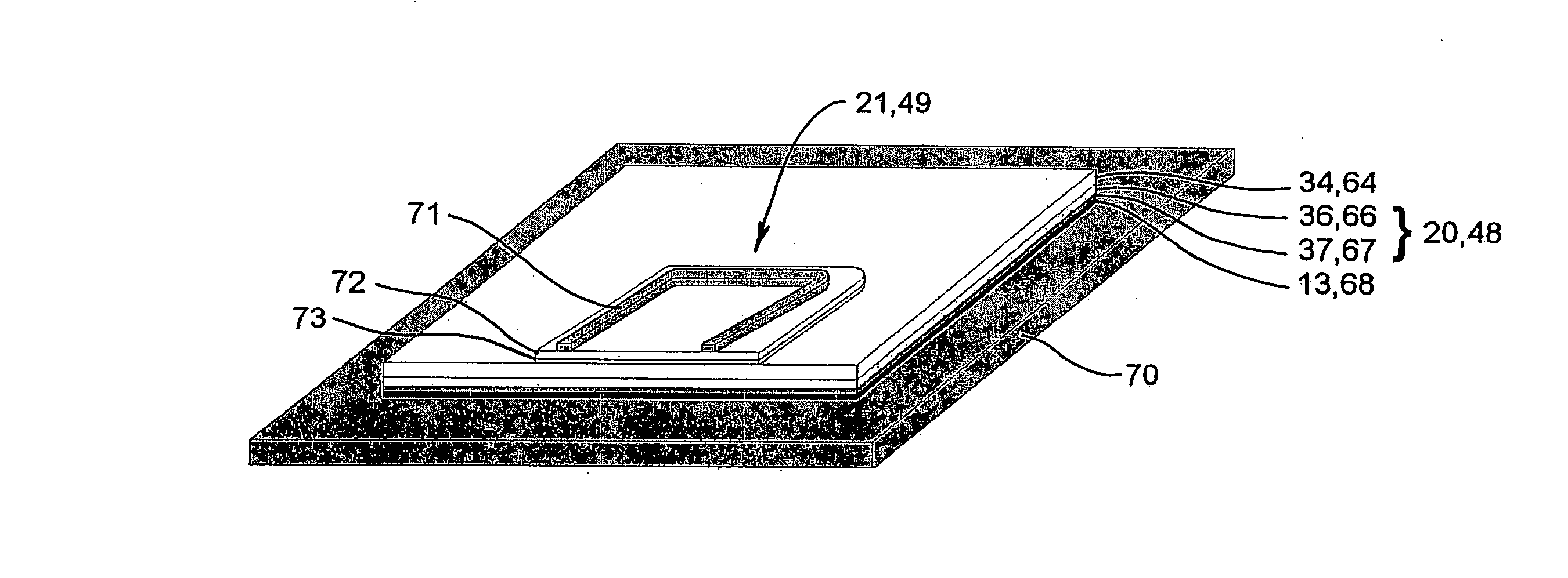
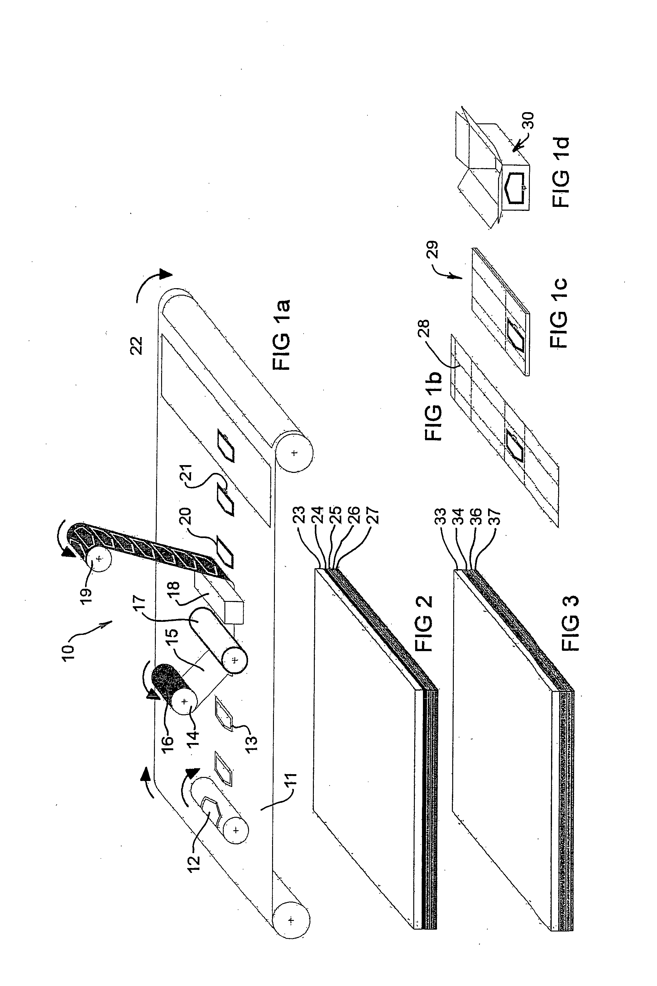
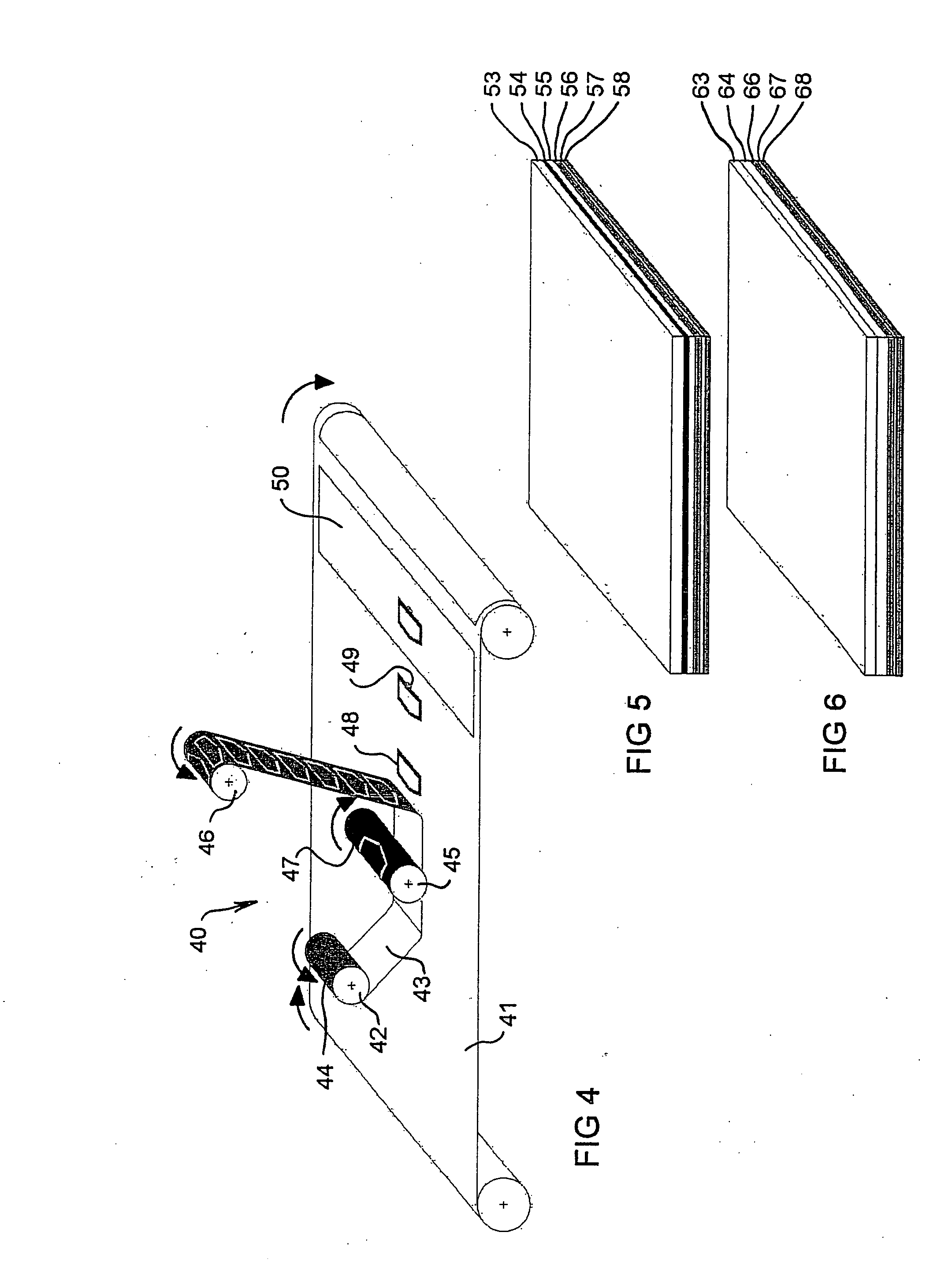
[0031]FIG. 1a shows a cardboard roll manufacturing process including a cold stamping apparatus 10 for manufacturing an auxiliary antenna 20 for an RFID tag 21. The cold stamping apparatus 10 shown in FIG. 1a is adapted to apply a relatively thin antenna (approximately not more than about 5 μm) to a cardboard surface 11 in the cardboard roll manufacturing process. The cold stamping apparatus 10 includes an offset printing roll 12 for applying to the surface 11 of the cardboard roll a suitable adhesive 13 in a shape corresponding to the auxiliary antenna. The apparatus 10 includes a roller 14 for supplying continuous webstock 15 including a conductive film 16. The conductive film 16 is applied to the surface 11 of the cardboard roll by means of a pressing roller 17 and a source 18 of ultra violet (UV) light for irradiating the film prior to being taken up by a roller 19.

[0032]Pressure applied by roller 17 causes the conductive film 16 to adhere to the adhesive 13 in the shape correspo...


PUM

PropertyMeasurementUnit
Fractionaaaaaaaaaa
Fractionaaaaaaaaaa
Resistance per lengthaaaaaaaaaa

Abstract

A method is disclosed of forming on a moving surface an auxiliary antenna for an RFID tag. The method includes the steps of providing a webstock of polymeric material including a conductive film, conveying the webstock with the moving surface, and applying the conductive film to the moving surface in a shape corresponding to the auxiliary antenna. The moving surface may include cardboard in a roll manufacturing process. Depending on the thickness of the auxiliary antenna the step of applying the conductive film may include cold or hot stamping. Apparatus for forming an auxiliary antenna for an RFID tag is also disclosed.

Description

CROSS-REFERENCE TO RELATED APPLICATIONS[0001]This application claims the benefit of the filing date of U.S. Provisional Patent Application No. 60 / 852,352 filed Oct. 17, 2006, the disclosure of which is hereby incorporated herein by reference.FIELD OF THE INVENTION[0002]The present invention relates to the field of Radio Frequency Identification (RFID) tags and in particular relates to a method and apparatus for manufacturing an auxiliary antenna for an RFID tag.BACKGROUND OF THE INVENTION[0003]RFID tags are used to associate an object with information stored in the tag such as an identification code. The RFID tag is read via the principle of electromagnetic (EM) communication wherein an interrogator containing a transmitter generates an EM signal that is transmitted via an antenna associated with the interrogator to an antenna associated with the tag. In a passive tag the antenna receives a portion of the transmitted energy and through a rectifier generates DC power for operating a ...

Claims


Application Information

Patent Timeline
IPC IPC(8): G08B13/14H01Q1/40H01Q13/00
CPCG06K19/07749Y10T29/49016Y10T29/49117Y10T156/1075
Inventor MARTIN, PHILIPPELECIRE, PHILIPPE
Owner HID TEXTILE SERVICES SARL
Features
  • Generate Ideas
  • Intellectual Property
  • Life Sciences
  • Materials
  • Tech Scout
  • Unparalleled Data Quality
  • Higher Quality Content
  • 60% Fewer Hallucinations
Learn More