Apparatus and method of controlled delay packet forwarding

a technology of delay packet forwarding and apparatus, applied in electrical apparatus, digital transmission, data switching networks, etc., can solve the problems of transmission delay, transmission delay is the delay, and transmission delay is slowly varying, so as to achieve the effect of reducing the time of transmission delay

Active Publication Date: 2008-04-17
JUMIPER NETWORKS INC
View PDF24 Cites 57 Cited by
  • Summary
  • Abstract
  • Description
  • Claims
  • Application Information

AI Technical Summary

Benefits of technology

[0019]FIG. 4 illustrates the application of a controlled delay by the controlled delay packet forwarding functio...

Problems solved by technology

However, the timing accuracy of conventional NTPv4 implementations appear to be far from what is needed for distribution of Stratum 2 quality timing.
In packet networks the delays are primarily the station to station transmission delay over the physical media and transit hop delay.
Transmission delay is the delay due to the distance the signal travels at the speed of light over the associated physical media....

Method used


Image

  • Apparatus and method of controlled delay packet forwarding
  • Apparatus and method of controlled delay packet forwarding
  • Apparatus and method of controlled delay packet forwarding

Examples


Embodiment Construction

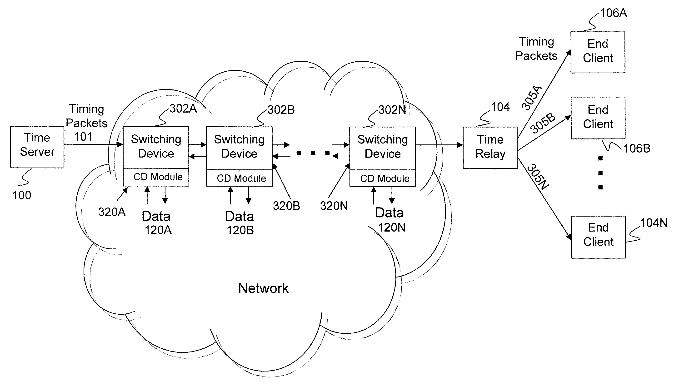
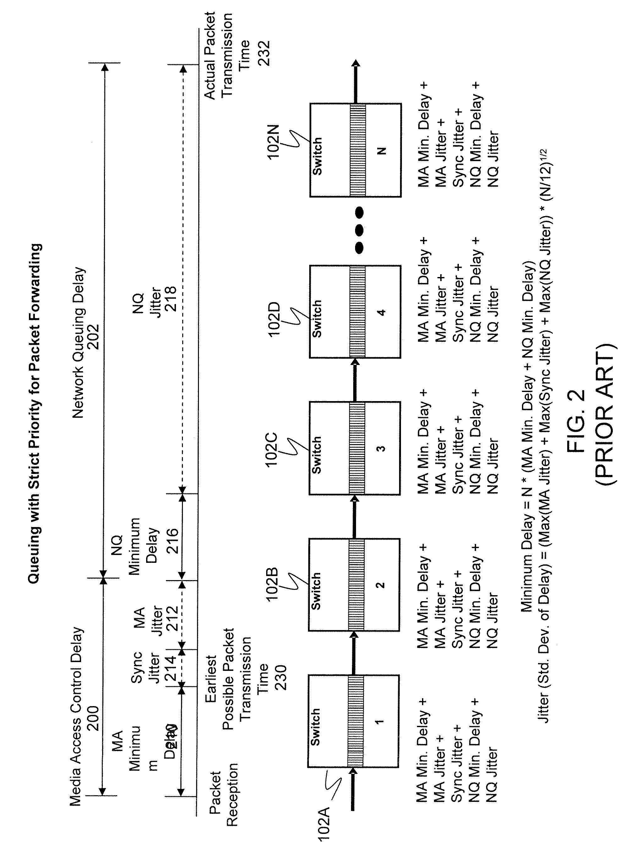
[0022] Controlled delay packet forwarding can eliminate most or all of the jitter per transit hop by trading off increased delay per hop with reduced jitter per hop. Controlled delay packet forwarding works by applying a sufficiently large controlled delay to controlled delay packets so that controlled delay packets do not experience the largest jitter sources per transit hop, such as MA jitter 212 or NQ jitter 218. This can ensure predictable delay and jitter for forwarding of controlled delay packets at each transit hop. Controlled delay packet forwarding is particularly useful for timing packets, such as NTP packets distributed from a time server, that have strict jitter accumulation requirements and that may traverse many transit hops. Using controlled delay packet forwarding, NTP unicast, manycast, multicast, and broadcast packets can be forwarded through each transit hop with nearly constant delay, and with small and statistically well-behaved jitter.

[0023]FIG. 3 illustrates ...


PUM


Abstract

An apparatus and method are described for forwarding of packets with controlled delay. In one embodiment, the invention includes controlled delay queuing logic to hold a packet in a first class for a queuing time of at least a controlled delay value, and scheduling logic to determine whether to delay transmission of a packet in a second class to allow the transmission of the packet in the first class when the queuing time reaches the controlled delay value.

Description

CROSS-REFERENCE TO RELATED APPLICATIONS [0001] This application claims priority to U.S. Provisional Application Ser. No. 60 / 839,465, filed Aug. 22, 2006, which is incorporated by reference in its entirety.FIELD OF THE INVENTION [0002] The present invention relates generally to processing of packet traffic in computer networks. More particularly, this invention is directed towards forwarding packets with controlled delay at each network device to minimize the accumulation of jitter. BACKGROUND OF THE INVENTION [0003] In recent years, there has been a rapid increase in demand for delivery of real-time applications and services in computer networks, including Pseudo-Wire Emulation (PWE), Voice over IP (VoIP), video conferencing, and broadcast, multicast and manycast streaming services such as H.261, H.323, and IPTV. These real-time services may require highly accurate timing to ensure high service quality. For example, it is desirable to eliminate data loss due to clock mismatch betwee...

Claims


Application Information

Patent Timeline
IPC IPC(8): H04J3/06H04L47/22H04L47/32H04L47/56
CPCH04L12/5693H04L47/564H04L47/283H04L47/10H04L47/50
Inventor BARRY, CHARLES F.SHEN, TIANPAN, FENG F.SUBRAMANIAN, MEENAKSHINGUYEN, HANK P.
Owner JUMIPER NETWORKS INC
Why Eureka
Try Eureka