
High energy short pulse fiber laser achieved by combining pulse shaping, polarization shaping and spectral shaping

Inactive Publication Date: 2008-04-17
POLARONYX
View PDF19 Cites 27 Cited by
  • Summary
  • Abstract
  • Description
  • Claims
  • Application Information

AI Technical Summary

Benefits of technology

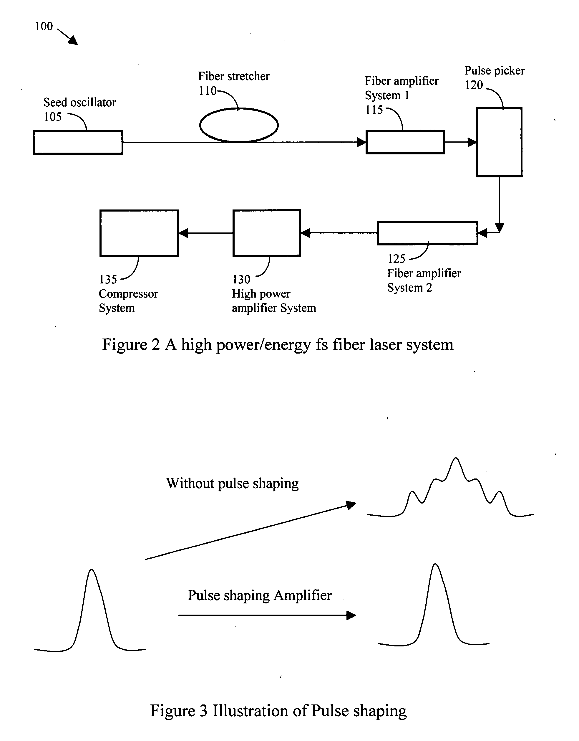
[0005] It is therefore an object of the present invention to provide system configurations and methods for applying the combinations of pulse shaping, spectral shaping and polarization shaping in different stages of a high-energy ultra-short pulse fiber laser system to manage and reduce the nonlinear effects. By combining the pulse shaping, spectral shaping and polarization shaping, a short pulse of <200 fs) and high energy, e.g., 100 uJ to over mJ, fiber laser with average power from 1 W to 100 W is achievable and the above discussed difficulties and limitations can be resolved.

Problems solved by technology

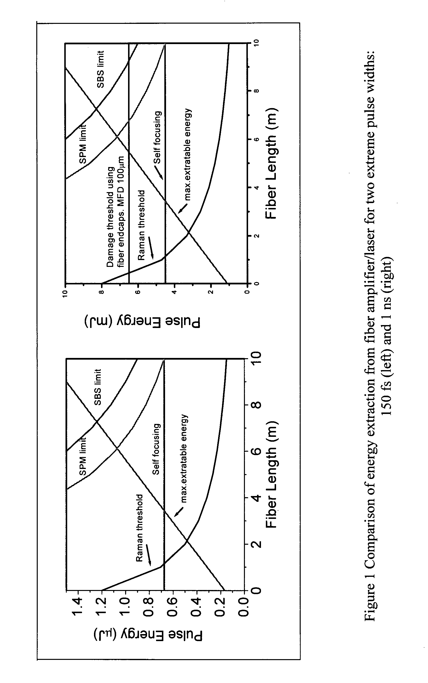
Conventional approaches to achieve micro-Joul pulse, such as chirped pulse generation and amplification are still limited by the third order dispersion (TOD), SPM that causes the frequency chirping, and also the gain narrowing effects.

Method used


Image

  • High energy short pulse fiber laser achieved by combining pulse shaping, polarization shaping and spectral shaping
  • High energy short pulse fiber laser achieved by combining pulse shaping, polarization shaping and spectral shaping
  • High energy short pulse fiber laser achieved by combining pulse shaping, polarization shaping and spectral shaping

Examples


Embodiment Construction

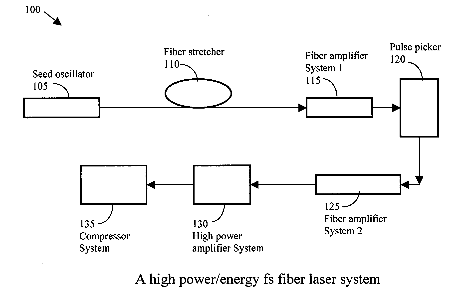
[0024] Referring to FIG. 2 for a schematic diagram of a fiber laser system 100 of this invention to implement a method of combining polarization shaping, spectral shaping and / or pulse shaping in a high energy short pulse laser system to eliminate the nonlinear effects and the third order dispersions (TOD), the frequency chirping caused by SPM and the gain narrowing effects. The high-energy short pulse laser system includes a seed oscillator 105 for generating a seed laser with a 20-100 MHz repetition rate femtosecond pulses. The seed laser is projected to a fiber stretcher 110 for stretching the pulse width in a range from one hundred ps to 10 ns. The stretched laser pulse is then transmitted to a fiber amplifier system 1, amplifier system 115 to amplify the stretched pulse to a high power of a few hundreds of mW. The amplified laser is then processed through a pulse picker 120 in down selection of repetition rate from tens of kHs (10 kHz) to several MHz and then projected to a fibe...


PUM


Abstract

A fiber laser system includes a fiber mode-locking oscillator, a fiber stretcher, a multistage amplifier chain, a pulse picker, and a compressor wherein at least a device for performing a pulse shaping, a spectral shaping and a polarization shaping and a combination thereof is implemented in the fiber mode-locking oscillator, the fiber stretcher, the multistage amplifier chain, the pulse picker, and the compressor for managing and reducing nonlinear effects in the fiber laser system. The combinations of pulse shaping, spectral shaping and polarization shaping in different stages of the fiber laser system enables the fiber laser system to generate a short pulse of <200 fs and a high energy laser in a range between 1 uJ to over mJ and an average power from 1 W to 100 W.

Description

[0001] This Formal Application claims a Priority Date of May 15, 2006 benefit from a Provisional Patent Applications 60 / 800,327 filed by the same Applicant of this Application. The disclosures made in 60 / 800,327 are hereby incorporated by reference in this patent application.FIELD OF THE INVENTION [0002] The present invention relates generally to apparatuses and methods for providing high-energy short pulse fiber laser. More particularly, this invention relates to new configurations and methods for providing a high-energy short pulse fiber laser by combining pulse shaping, polarization shaping and spectral shaping. BACKGROUND OF THE INVENTION [0003] Short pulse high-energy fiber layer, for example a laser with a pulse of less than 200 fs and an energy level substantially between 100 uJ to over mJ, is still a challenge to all the researchers and engineers. FIG. 1 illustrates the comparison of energy extraction from fiber amplifier / laser for two extreme pulse widths; i.e., 150 fs and ...

Claims


Application Information

Patent Timeline
IPC IPC(8): H01S3/30
CPCH01S3/0057H01S3/067H01S3/06725H01S3/2316H01S3/06754H01S3/094007H01S3/1618H01S3/06741
Inventor LIU, JIAN
Owner POLARONYX
Learn More