

Positioning system
a positioning system and frequency deviation technology, applied in the field of positioning systems, can solve the problems of improving positioning accuracy, reducing the accuracy of positioning, so as to achieve high accuracy of time difference, high accuracy of measurement, and low power consumption
- Summary
- Abstract
- Description
- Claims
- Application Information
AI Technical Summary
Benefits of technology
Problems solved by technology
Method used
Image

Examples
first embodiment
[0036]In FIGS. 1 to 12, inclusive, a description regarding a receiving device and a positioning system using the same, related to Embodiment 1 of the present invention, is given. First, a description regarding an outline of the configuration and operation of the system of Embodiment 1 is given in FIGS. 1 to 3, inclusive.
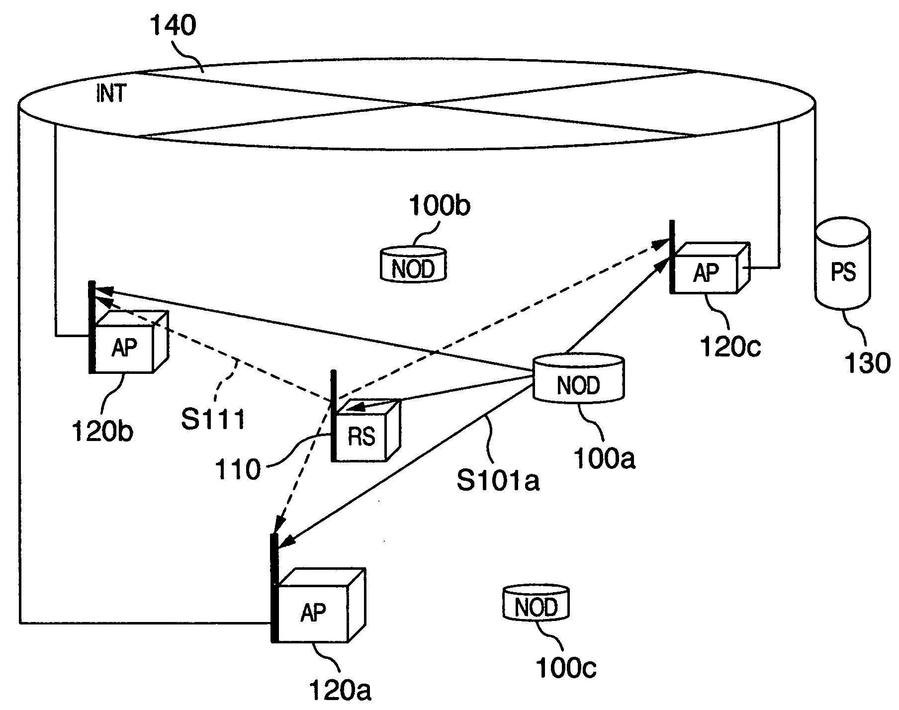
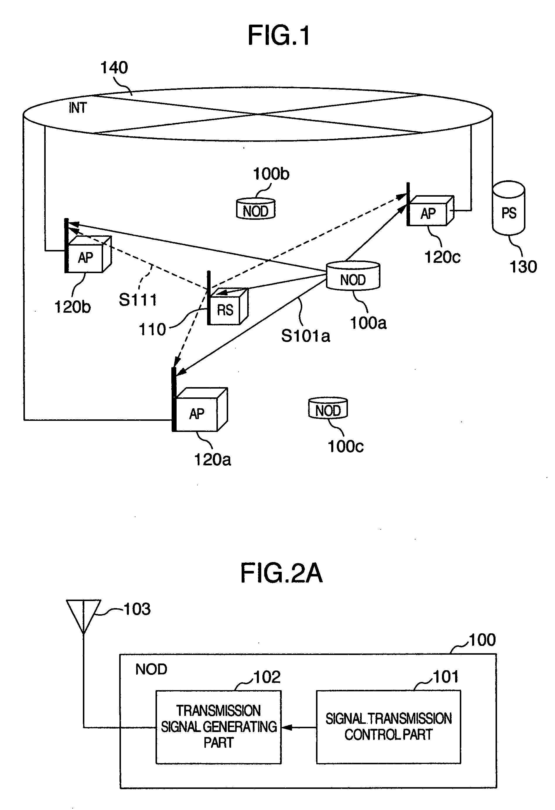
[0037]FIG. 1 shows the configuration of a positioning system related to Embodiment 1 of the present invention. The positioning system is composed of a plurality of nodes (NOD) 100 (100a, 100b, . . . ) (being the object of the positioning) that transmit positioning signals, a reference station (RS) 110 transmitting reference signals, a plurality of base stations (AP) 120 (120a, 120b, and 120c) receiving positioning signals and reference signals, a positioning server (PS) 130, and a network (INT) 140 connecting each base station 120 and positioning server 130. Further, the reference numeral indices a, b, and c are taken to indicate the same kind of constitutive element...
second embodiment
[0157]Also, as an example of a receiving device in a base station, the description was carried out using a device making an analog-to-digital conversion of a received impulse sequence with the pulse repetition period, but the time difference measurement method and the deviation measurement method related to the present invention are not ones limited to this device.
[0158]E.g., as a positioning system of Embodiment 2 of the present invention, it is valid to adopt, for a communication system using a method of taking the correlation between a template wave shape and a received signal and capturing the synchronization thereof, a receiving device using a time difference and deviation measurement method similar to that of Embodiment 1.
[0159]In FIG. 14, there is shown a configuration example of a receiving device 200 related to Embodiment 2 of the present invention. The receiving device is provided with: a template wave form generating part 202; a timing shift part 203 shifting the timing (...
third embodiment
[0163]Further, this far, there has been carried out a description of a time difference measurement method for transmission signals from different transmitting devices, but the time difference measurement method of the present invention is not limited thereto. E.g., in case a first transmission signal and a second transmission signal are transmitted from the same transmitting device, it is valid to adopt a receiving device using a time difference and deviation measurement method similar to that of Embodiment 1.
[0164]In this case, the time difference measured in the receiving device corresponds to the distance moved after the transmitting device has transmitted the first transmission signal until the second transmission signal is transmitted. That is to say that by receiving, with a receiving device related to the present invention, the first transmission signal and the second transmission signal transmitted from the same transmitting device, it becomes possible to measure a relative ...
PUM
 Abstract
Description
Claims
Application Information