Torque transfer system, method of using the same, method of fabricating the same, and apparatus for monitoring the same

Inactive Publication Date: 2008-04-17
CAMEL CLUB
View PDF5 Cites 11 Cited by
  • Summary
  • Abstract
  • Description
  • Claims
  • Application Information

AI Technical Summary

Benefits of technology

[0008]An object of the present invention is to provide a system and method for transferring rotational motion and torque that prevents generation of noise, friction, and heat.
[0009]Another object of the present invention is to provide a system and method for improving the transferring of rotational motion and torque.
[0010]Another object of the present invention is to provide a method of fabricating a system for improving the transferring of rotational motion and torque.
[0011]Another object of the present invention is to provide a system and method for transferring rotational motion and torque that accommodates large amounts of shaft misalignment.

Problems solved by technology

However, due to mechanical friction between the mechanically interconnected members, significant amounts of heat are generated that causes premature failure of the mechanically interconnected members and increases costs and loss of productivity due to repairs.
Moreover, although the mechanical friction may be reduced by supplying a lubricant to the mechanically interconnected members, operational speed of the interconnected members has a maximum upper limit, thereby severely limiting transfer of the rotational motion between the first and second rotational shafts.
In addition, any misalignment of the first and second rotational shafts will result in a transfer of corresponding shearing stresses to the interconnected members.
Finally, the interconnected members generate a significant amount of noise due to the mechanical interaction.

Method used


Image

  • Torque transfer system, method of using the same, method of fabricating the same, and apparatus for monitoring the same
  • Torque transfer system, method of using the same, method of fabricating the same, and apparatus for monitoring the same
  • Torque transfer system, method of using the same, method of fabricating the same, and apparatus for monitoring the same

Examples


Embodiment Construction

[0071]Reference will now be made in detail to the preferred embodiments of the present invention, examples of which are illustrated in the accompanying drawings.

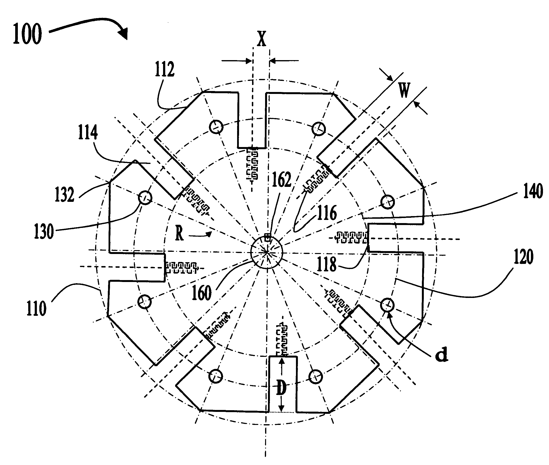
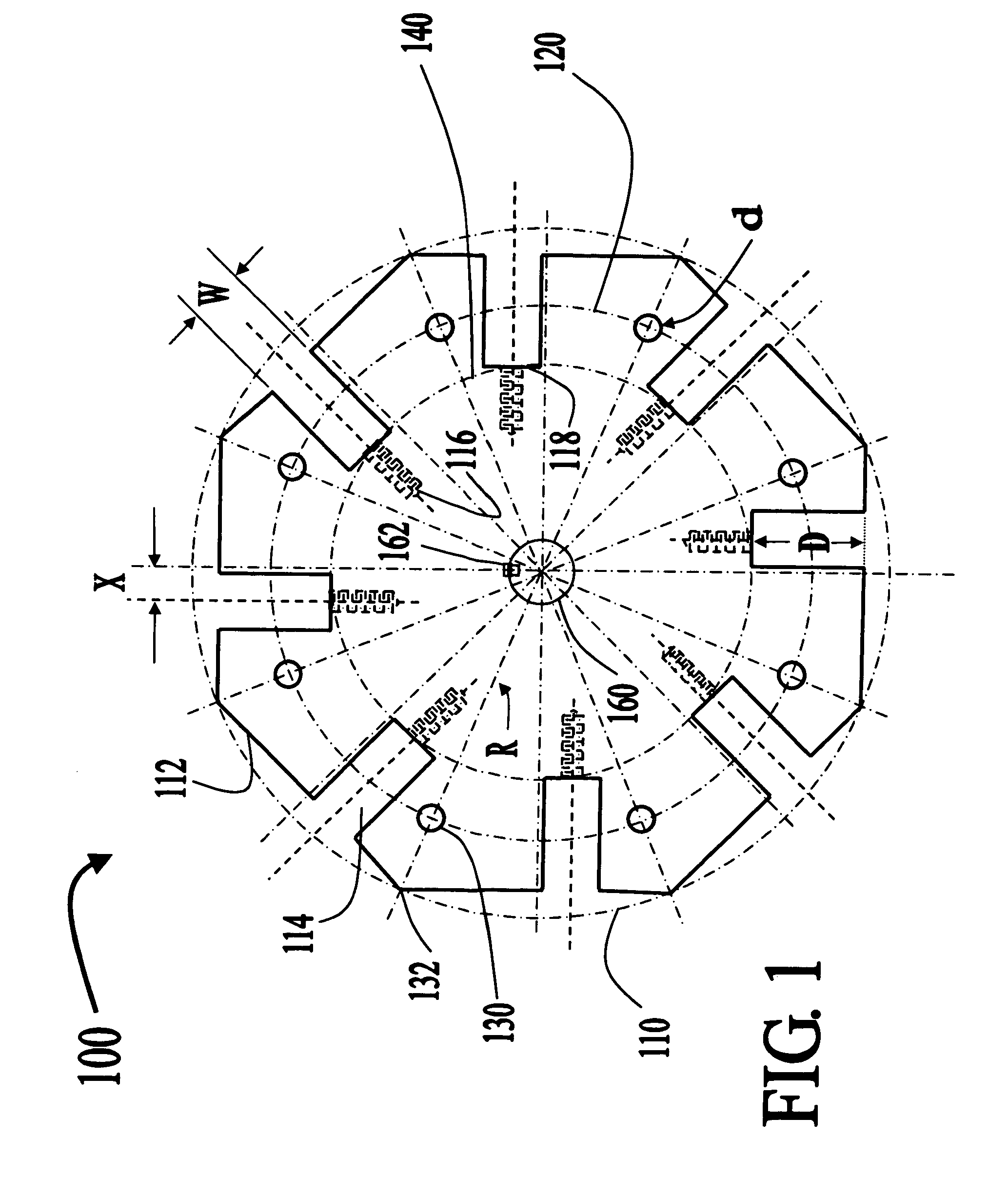
[0072]FIG. 1 is a plan view of an exemplary rotary plate according to the present invention. In FIG. 1, a rotary plate 100 may have a major diameter 110, a minor diameter 140, major outer surfaces 112, alignment holes 130, and a through hole 160. Each of the major outer surfaces 112 may include at least one channel region 114 that extends from the major outer surface 112 to the minor diameter 140 by a depth D. Accordingly, the channel regions 114 are radially disposed along the rotary plate 100 and are offset from the radius of the rotary plate 100 by a distance X, and each channel region may have a width W. In addition, the through hole 160 is disposed at a center of the rotary plate 100 and may include a keyway 162 for coupling to a rotational shaft (not shown).

[0073]In FIG. 1, each of the channel regions 114 include a thr...


PUM


Abstract

A system for transferring torque includes a first rotary plate coupled to a first rotational shaft extending along a first axial direction from a first plane of rotation of the first rotary plate, and a second rotary plate coupled to a second rotational shaft disposed along a second axial direction from a second plane of rotation of the second rotary plate, the second rotary plate spaced apart from the first rotary plate, wherein the first rotary plate is magnetically coupled to the second rotary plate by a plurality of magnet holding members, such that the torque applied to the first rotational shaft is transferred to the second rotational shaft.

Description

BACKGROUND OF THE INVENTION[0001]1. Field of the Invention[0002]The present invention relates to a torque transfer system, a method of using a torque transfer system, a method of fabricating a torque transfer system, and an apparatus for monitoring a torque transfer system, and more particularly, to a system and a method for transferring torque between physically disconnected rotating shafts, a method of fabricating a torque transfer system for transferring torque between physically disconnected rotating shafts, and an apparatus for monitoring the system.[0003]2. Discussion of the Related Art[0004]In general, transmission of rotational motion is accomplished by coupling rotating shafts using a combination of physically connected members. For example, in order to transfer rotational motion from a first rotational shaft to a second rotational shaft, gears, belts, or chain members are connected to the first and second rotational shafts and mechanically interconnected. However, due to m...

Claims


Application Information

Patent Timeline
IPC IPC(8): F16H13/12
CPCH02K49/106H02K49/102
Inventor WISE, RICHARD J.RICHARDS, WILLIAM R.SNAIDER, RICHARD P.NEVIN, HOWARD L.
Owner CAMEL CLUB
Why Eureka
Try Eureka