Surgical probe and method of making

a surgical and probe technology, applied in the field of surgical probes, can solve the problems of many challenges, reduced or even no direct visualization, and the development of less invasive surgical methods and devices

Inactive Publication Date: 2008-04-17
BAXANO
View PDF99 Cites 55 Cited by
  • Summary
  • Abstract
  • Description
  • Claims
  • Application Information

AI Technical Summary

Benefits of technology

[0016] These and other aspects and embodiments are described more ...

Problems solved by technology

Developing less invasive surgical methods and devices, however, can pose many challenges.
For example, some challenges of less invasive techniques include working in a smaller operating field, working with smaller devices, and trying to operate with reduced or even no direct visualization of the structure (or structures) being treated.
These challenges are compounded by the fact that target tissues to be modified often reside very close to one or more vital, non-target tissues, which the surgeon hopes not to damage.
Two initial obstacles in any given minimally invasive procedure, therefore, are accessing a desired location within the patient and positioning a minimally invasive surgical device in the location to perform the procedure on one or more target tissues, while avoiding damage to nearby non-target tissues.
In a patient, this may manifest as pain, impaired sensation and/or loss of strength or mobility.
Epidural steroid injections may also be utilized, but they do not provide long lasting benefits.
When these approaches are inadequate, current treatment for spinal stenosis is generally limited to invasive surgical procedures to remove ligament, cartilage, bone spurs, synovial cysts, cartilage, and bone to provide increased room for neural and neurovascular tissue.
Removal of vertebral bone, as occurs in laminectomy and facetectomy, often leaves the effected area of the spine very unstable,...

Method used


Image

  • Surgical probe and method of making
  • Surgical probe and method of making
  • Surgical probe and method of making

Examples


Embodiment Construction

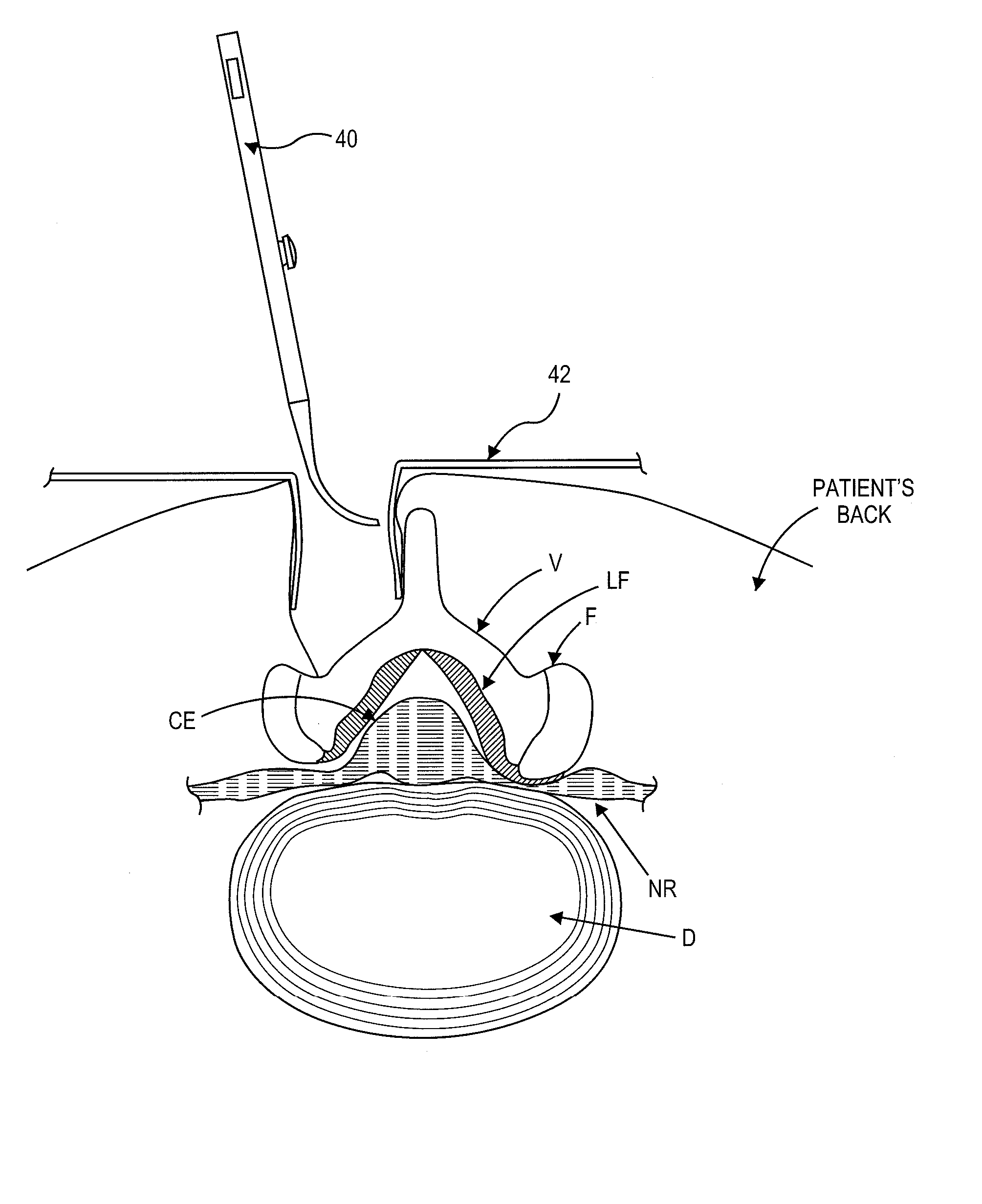
[0033] Various embodiments of a surgical probe and method for making same are provided. Although the following description and accompanying drawing figures generally focus on use of a probe in the spine, in alternative embodiments, the described probes or variations thereof may be used in any of a number of other anatomical locations in a patient's body.

[0034] Referring to FIG. 4, one embodiment of a guidewire system 10 is shown coupled with a tissue cutting device 11 in position within a patient's spine. Further description of various embodiments of cutting device 11 may be found in U.S. patent application Ser. No. 11 / 461,740, entitled “Multi-Wire Tissue Cutter” (Attorney-Docket No. 026445-000900US), and filed Aug. 1, 2006, the full disclosure of which is hereby incorporated by reference. A number of alternative embodiments of cutting devices, many of which may be used (or adapted for use) with guidewire system 10, are further described in U.S. patent application Ser. Nos.: 11 / 375...


PUM

PropertyMeasurementUnit
Angleaaaaaaaaaa
Diameteraaaaaaaaaa
Flexibilityaaaaaaaaaa

Abstract

A method for making a probe for placing a guidewire between two tissues in a patient's body may involve forming at least one bend in a thin, rigid tube having a proximal end and a distal end, flattening at least part of the tube closer to the distal end than the proximal end, and removing a portion of the upper surface of the flattened part of the tube to form an aperture. A probe for placing a guidewire between two tissues in a patient's body may include: a thin, rigid tube having a proximal straight portion, a flattened distal portion, a bend disposed between the proximal and distal portions, and a lumen passing through the proximal portion and at least part of the distal portion; and a curved, flexible tubular member disposed at least partially within the lumen of the tube.

Description

CROSS-REFERENCE TO RELATED APPLICATIONS [0001] The present application claims priority under 35 U.S.C. §119 to U.S. Provisional Patent Application 60 / 823,594, entitled “Surgical Probe and Method of Making” filed Aug. 25, 2006 which is incorporated herein by reference in its entirety.BACKGROUND OF THE INVENTION [0002] The present invention relates generally to medical / surgical devices and methods. More specifically, the present invention relates to a surgical probe and method for making same. [0003] In recent years, less invasive (or “minimally invasive”) surgical techniques have become increasingly more popular, as physicians, patients and medical device innovators have sought to achieve similar or improved outcomes, relative to conventional surgery, while reducing the trauma, recovery time and side effects typically associated with conventional surgery. Developing less invasive surgical methods and devices, however, can pose many challenges. For example, some challenges of less inv...

Claims


Application Information

Patent Timeline
IPC IPC(8): A61B17/00
CPCA61B17/0206A61B17/1671A61B17/320016A61B17/3415Y10T29/49995A61B2017/00261A61B2017/00469A61B2017/22038A61B2017/32006A61B17/3468
Inventor SCHMITZ, GREGORYLEGUIDLEGUID, RON
Owner BAXANO
Why Eureka
Try Eureka