Bar feeder, feed rod vibration prevention support of material feeder and vibration stopper of material feeder

Active Publication Date: 2008-04-24
ALPS TOOL
View PDF16 Cites 14 Cited by
  • Summary
  • Abstract
  • Description
  • Claims
  • Application Information

AI Technical Summary

Benefits of technology

[0019]The invention is directed to a feed rod vibration prevention support in a bar feeder improved in vibration prevention performance of the feed rod.

Problems solved by technology

Because of this reason, the oil reaches the neighbouring oil reservoir through this slight gap, so that it is difficult for the oil to reach the neighbouring oil reservoir, thereby reducing the vibration prevention effect due to the oil.
However, these machines or like are not provided with any mechanism for adjusting an open / close angle of the frames so as to accord with the material diameter.
The upper and lower frames must be adjusted independently, which, however, is not easily performed.
Especially, in a case where the lower and side surfaces of the upper and lower frames are covered by covers or like, it is predicted to be difficult to adjust the lower frame.
However, the upper and lower frames are used in the closed state, and this stopper is not provided with any mechanism for adjusting the open / close angle of the upper and lower frames so as to accord with the material diameter.
However, a structure including such two cylinders is complicated and the vibration stopper is firmly fixed to a body.
Further, at the time when the bar material is fed from the material rack into the U-shaped groove of the support portion in the bar feeder, the bar material rolls down into the U-shaped groove, so that an impact, noise or like may be caused by the collision of the bar material with the support portion.
For example, in a case where the bar material is erroneously fed into the U-shaped groove by a miss-operation of an operator, it is extremely difficult to take out the bar material from the U-shaped groove.
This difficulty will be increased in a case the diameter of the bar material becomes near the width of the U-shaped groove.

Method used


Image

  • Bar feeder, feed rod vibration prevention support of material feeder and vibration stopper of material feeder
  • Bar feeder, feed rod vibration prevention support of material feeder and vibration stopper of material feeder
  • Bar feeder, feed rod vibration prevention support of material feeder and vibration stopper of material feeder

Examples


first embodiment

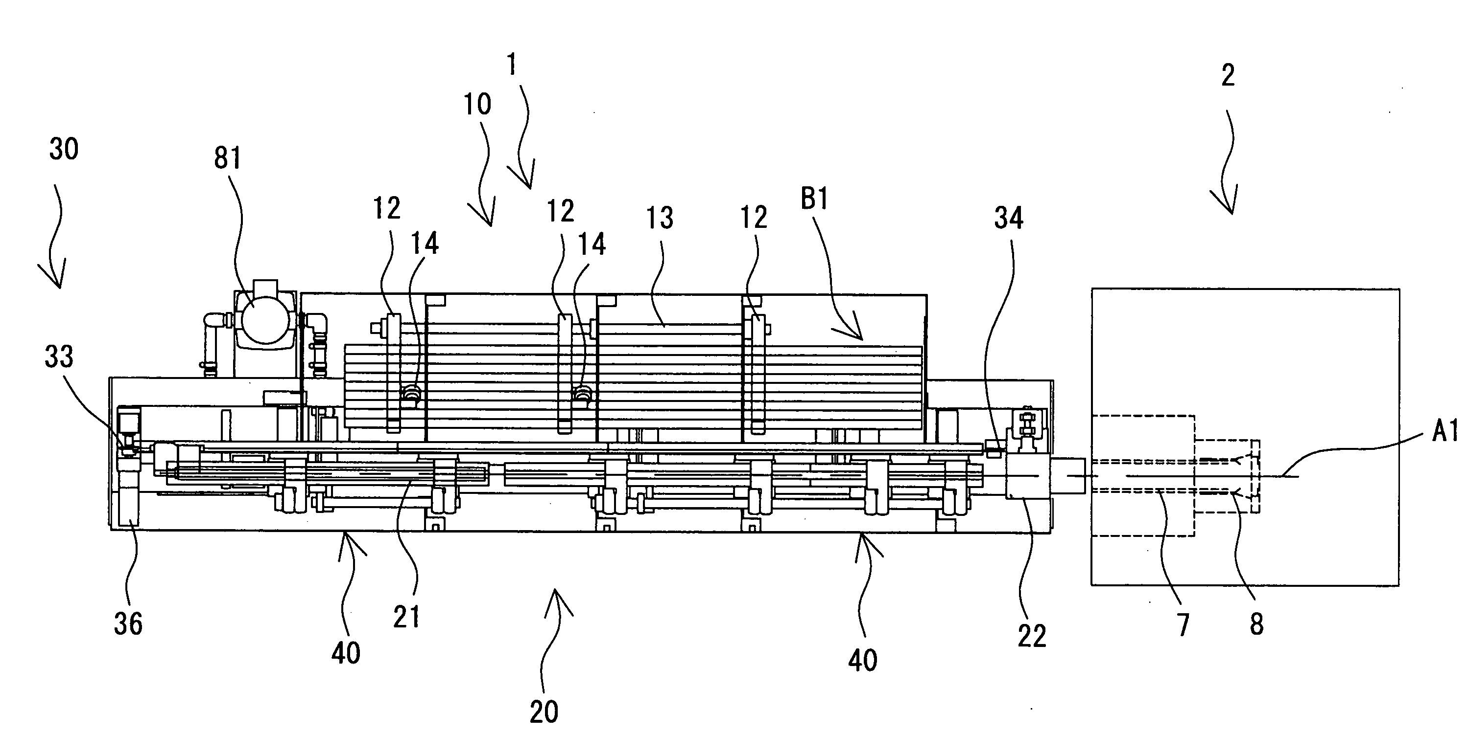
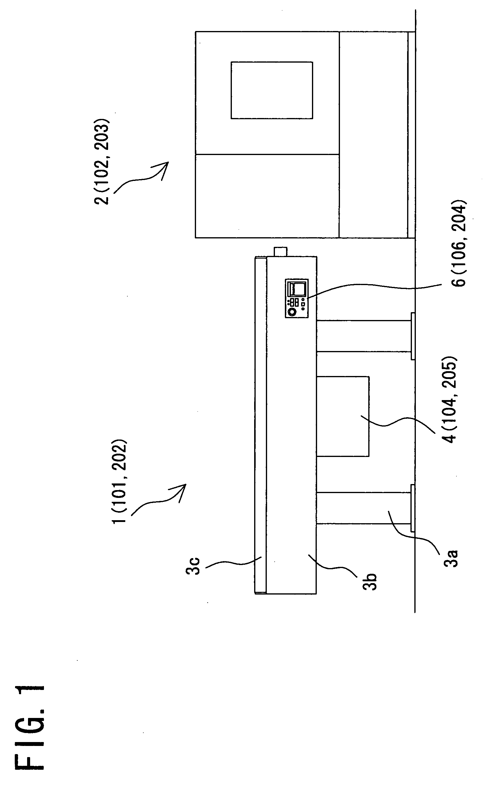
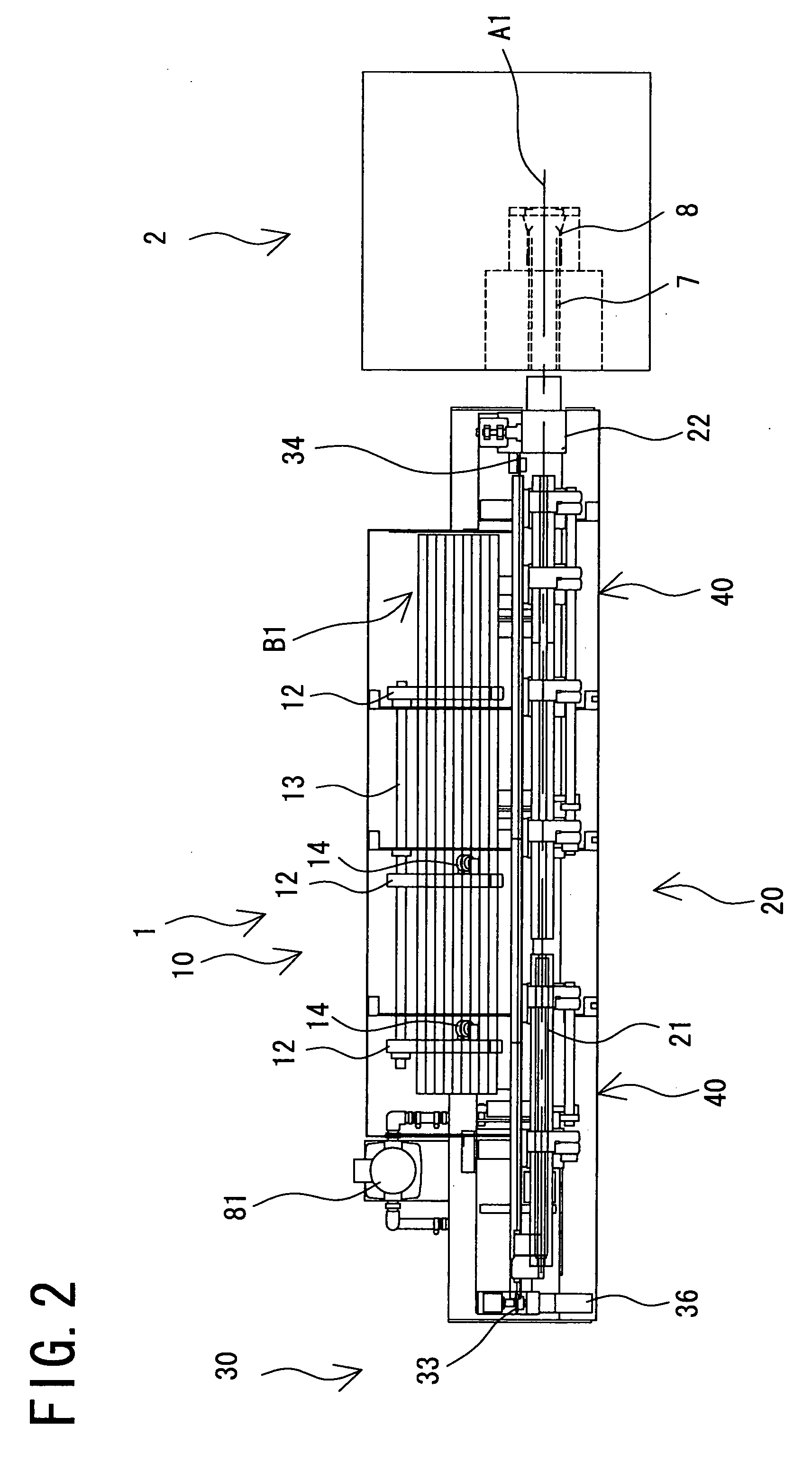
[0061]With reference to FIG. 1, a bar feeder 1 as a material feeder is located adjacent to a lathe 2 as a working machine. The bar feeder 1 includes a feeder body 3b supported by a base 3a. The bar feeder 1 includes an upper lid 3c assembled with the feeder body 3b. The bar feeder 1 further includes a control box 4 located below the feeder body 3b and an operation board 6 located in front of the feeder body 3b. With reference to FIG. 2, the lathe 2 is provided with a cylindrical spindle (main shaft) 7 through which a bar material B1 may pass, and the lathe 2 is also provided, at the end of the spindle 7, with a chuck 8 for grasping the bar material B1. The chuck 8 is linearly moved together with the spindle 7 and is rotatable around an axis A1 of the spindle 7. The lathe 2 has a blade for cutting the front end of the bar material B1. The spindle 7 may be a stationary type which is not linearly movable.

[0062]Further, with reference to FIG. 2, the bar feeder 1 includes a material rack...

second embodiment

[0084]The bar feeder 1 according to the second embodiment will be described hereunder with reference to FIG. 7.

[0085]The bar feeder 1 includes a guide device 50A which has a characteristic feature of the invention. The guide device 50A includes a J-shaped lower support guide 56A. The lower support guide 56A is composed of a bottom wall section 56A1, a first side wall section 56A2 extending at right angle from one end of the bottom wall section 56A1, and a second side wall section 56A3 extending at right angle from the other end of the bottom wall section 56A1. The second side wall section 56A3 has a length longer than that of the first side wall section 56A2. The lower support guide 56 is provided with a right-angled corner members 56A4 and 56A5 constituted by the bottom wall section 56A1 and the first and second side wall sections 56A2 and 56A3. The guide device 50A includes an L-shaped upper support guide 58A in combination with the lower support guide 56. The upper support guide ...

third embodiment

[0089]With reference to FIGS. 8 and 9, a bar feeder 101 as a material feeder is located in adjacent to a lathe 102 as a working machine. The bar feeder 101 includes a feeder body 103b supported by a base 103a. The bar feeder 101 includes an upper lid 103c assembled with the feeder body 103b. The bar feeder 101 includes a control box 104 located below the feeder body 103b. The bar feeder 101 includes an operation board 106 located at the front side portion of the feeder body 103b. With reference to FIG. 8, the lathe 102 includes a cylindrical spindle 107 through which the bar material B1 passes. The lathe 102 also includes, at the end of the spindle 107, a chuck 108 for grasping the bar material B1. The chuck 108 is linearly movable with the spindle 107 and rotatable about the axis A1 thereof. The lathe 102 further includes a blade for working the front end of the bar material B1. A stationary type spindle may be adopted instead of the movable type.

[0090]As illustrated in FIG. 8, the...


PUM

PropertyMeasurementUnit
Angleaaaaaaaaaa
Elasticityaaaaaaaaaa
Attenuation coefficientaaaaaaaaaa

Abstract

A feed rod vibration prevention support of a material feeder includes a guide device for guiding a feed rod moving to feed a material to a working machine, and a vibration attenuation mechanism for preventing the feed rod from being vibrated. The guide device further includes a guide and a bush supported by the guide having a feed rod placed thereon. The vibration attenuation mechanism includes a first elastic material located between the bush and the guide. The bush is provided with a flanged portion.

Description

CROSS-REFERENCE TO RELATED APPLICATIONS[0001]This application is based upon and claims the benefit of priority from Japanese Patent Applications No. 2006-288987 filed on Oct. 24, 2006, No. 2006-290759 filed on Oct. 26, 2006 and No. 2006-296238 filed on Oct. 31, 2006; the entire contents of which are incorporated herein by reference.BACKGROUND OF THE INVENTION[0002]1. Field of the Invention[0003]The invention relates to a bar feeder for feeding a bar material to a working machine such as lathe, to a feed rod vibration prevention support in a material feeder, and to a vibration stopper of the material feeder.[0004]2. Related Art[0005]A bar feeder of a related art includes a structure having a feed rod passing through a guide pipe in form of a U-groove or cylindrical pipe, or an oil feeder for supplying oil to such guide pipe.[0006]On the other hand, another automatic rod feeder includes an oil feeder having bushes fastened by screws in the U-groove guide at a predetermined interval. T...

Claims


Application Information

Patent Timeline
IPC IPC(8): B23B13/08B23Q16/00
CPCB23B13/08B23B2226/33Y10T82/2516Y10T82/2514Y10T82/2521
Inventor YAMAGUCHI, MITSUYOSHIKURIBAYASHI, SHIGEO
Owner ALPS TOOL
Why Eureka
Try Eureka