Gas Flow Control In A Ventilator

a gas flow control and ventilator technology, applied in the field of ventilators, can solve the problems of difficult to provide a control system that can quickly and accurately regulate the pressure, flow, or volume of gas using such techniques with a high level of stability, and achieve the effect of overcompensating the shortcomings of conventional ventilators, accurate, fast and stable control of pressure, flow

Active Publication Date: 2008-04-24
PHILIPS RS NORTH AMERICA LLC
View PDF3 Cites 72 Cited by
  • Summary
  • Abstract
  • Description
  • Claims
  • Application Information

AI Technical Summary

Benefits of technology

[0009]Accordingly, it is an object of the present invention to provide a ventilator that overcomes the shortcomings of conventional ventilators. This object is achieved according to one embodiment of the present invention by providing a ventilator that includes a source of gas, a conduit that carries the flow of gas to the airway of a patient, a first valve that controls a pressure, flow, or volume, of the flow of gas, a pressure sensor operatively coupled to the conduit between the valve and the patient and adapted to monitor a pressure of the flow of gas in the conduit, and a controller adapted to control the valve based on an output of th

Problems solved by technology

One disadvantage of conventional pressure/flow/volume control techniques, which is discussed in greater detail below, is that it is difficult for provi

Method used


Image

  • Gas Flow Control In A Ventilator
  • Gas Flow Control In A Ventilator
  • Gas Flow Control In A Ventilator

Examples


first embodiment

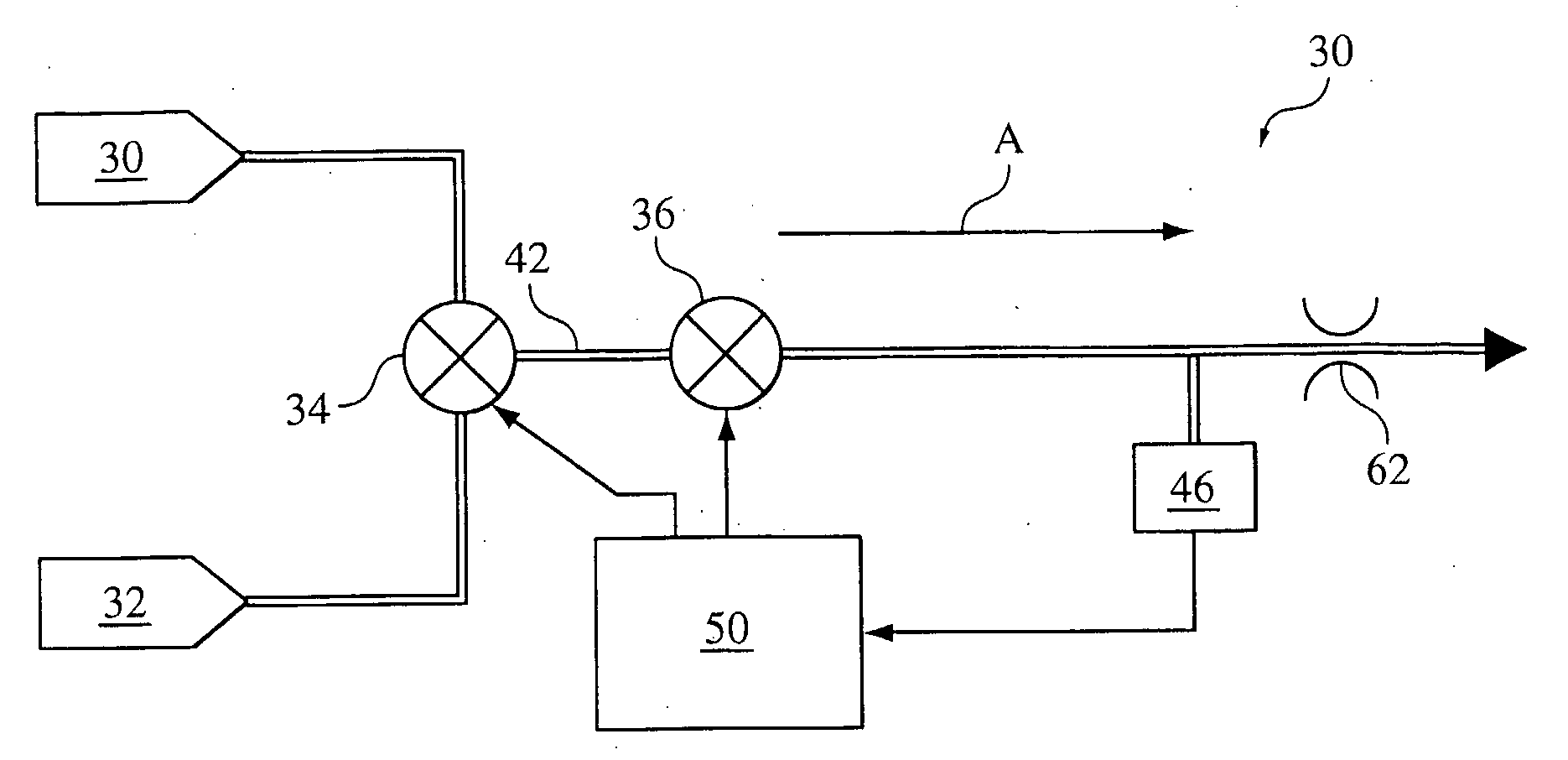
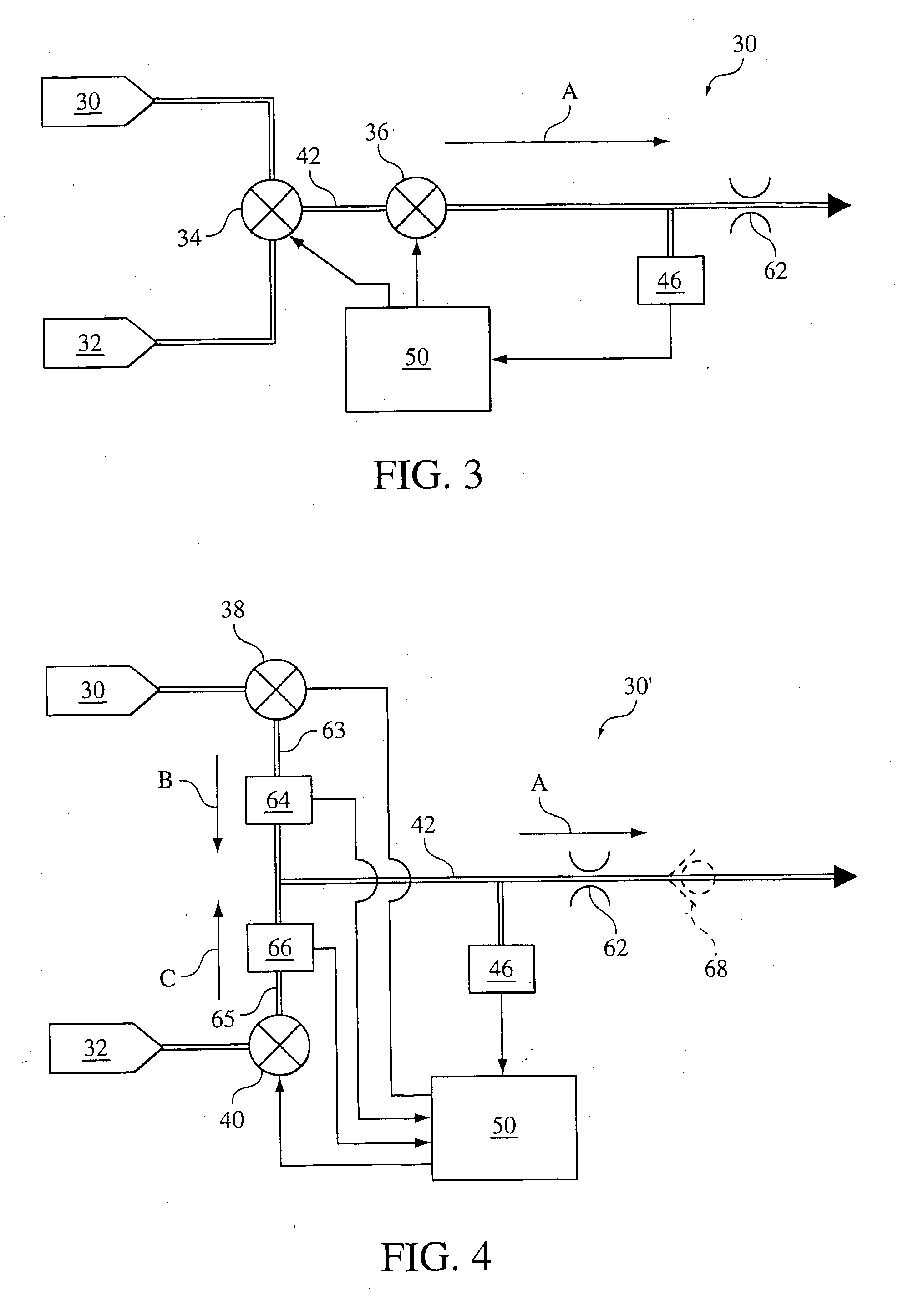
[0021]FIG. 3 is a schematic diagram of a ventilator 60 according to the principles of the present invention. It should be noted that FIG. 3 illustrates only those components of the ventilator associated with the delivery of a flow of gas to a patient during the inspiratory phase of the respiratory cycle. The expiratory components are omitted. It should be further understood that the present invention contemplates that ventilator 60 can be a pressure support system, such as a CPAP or bi-level system. Such systems are a single limb systems. Instead of an expiratory limb, an exhaust vent is provided at or near the patient in the inspiratory limb. Such systems do not include expiratory related components.

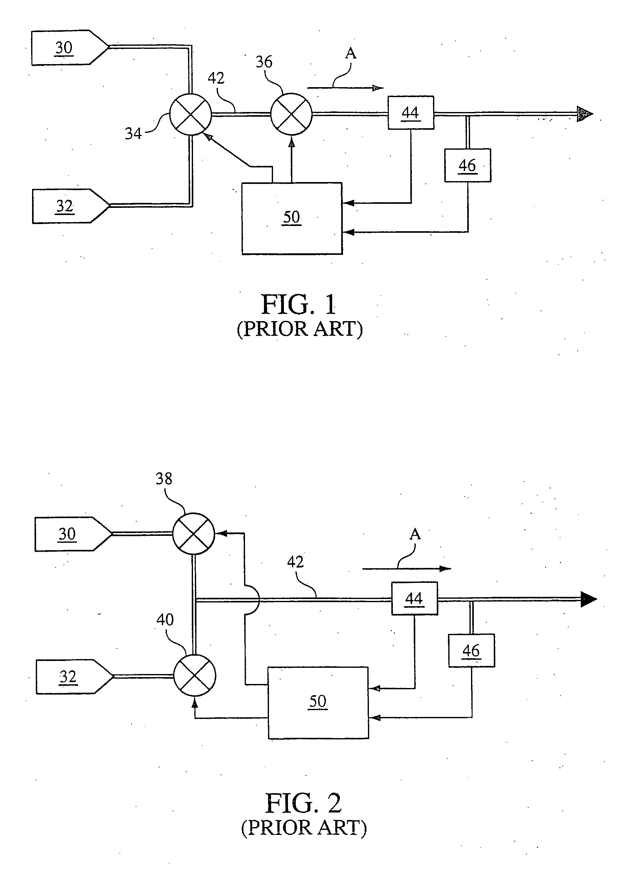
[0022]It can be appreciated from reviewing FIGS. 1 and 3, that the ventilator of the present invention is similar in many respects to a conventional ventilator. The main difference is the ventilator 60 includes a flow restrictor 62 provided in conduit 42 downstream of pressure / flow cont...

second embodiment

[0035]a ventilator 30′ according to the principles of the present invention is schematically illustrated in FIG. 4. In the embodiment, like that of the conventional ventilator shown in FIG. 2, two valves 38 and 40 are provided to control the flow of a first gas from first source 30 via gas flow path 63 and a second gas from second source 32 via gas flow path 65. The two gas flows, which are illustrated by arrows B and C are combined to define gas flow A for delivery to the user. In this embodiment, flow sensors 64 and 66 are disposed in the gas flow paths to monitor the direction and / or rate of flow of each gas prior to being mixed; Restrictor 62, as discussed above, is provided downstream of valves 64 and 66, and a pressure sensor is coupled to the gas flow path between valves 64 and 66 and restrictor 62.

[0036]Although not illustrated in this figure, the present invention contemplates that other sensors can be provided in the ventilatory system and used on fine-tune the control the...


PUM


Abstract

A ventilator or fluid delivery system that provides a flow of gas to an airway of a user. The ventilator includes a source of gas (30, 32), a conduit (63, 65, 42) that carries the flow of gas to the airway of a patient, a first valve (38, 40) that controls a pressure, flow, or volume, of the flow of gas, a pressure sensor (46) operatively coupled to the conduit between the valve and the patient and adapted to monitor a pressure of the gas in the conduit, and a controller (50) adapted to control the valve based on an output of the pressure sensor The ventilator further includes a restrictor (62) provided in the conduit between the pressure sensor and the patient. The restrictor, in essence, divides the fluid delivery system such that a first volume is defined in the conduit between the valve and the restrictor and a second volume is defined in the conduit between the patient and the restrictor, wherein the first volume is less than the second volume. The control system controls the pressure, flow, or volume relative to the first volume so that an accurate, fast, and stable control of the pressure, flow, or volume is achieved.

Description

PRIORITY CLAIM[0001]This application claims priority from Swedish Patent Application Ser. No. 0402120-0 filed Sep. 3, 2004.TECHNICAL FIELD[0002]The present invention pertains to a ventilator adapted to deliver a flow of gas to an airway of a user, and, in particular, to a ventilator with improved pressure control during inspiration.BACKGROUND OF THE INVENTION[0003]It is well known to utilize a ventilator, anesthesia machine, or pressure support device to deliver a fluid, such as oxygen, air, or other breathing gas or gas mixture, to an airway of patient to augment, supplement, or substitute the patient's own ventilatory effort and / or to treat the patient with a pressure support therapy. Of importance in such situations is the ability to accurately regulate or control the pressure, flow, and / or volume of gas delivered to the patient during the inspiratory phase of the respiratory cycle. For present purposes, the term “ventilator” is used to describe any system or device that delivers...

Claims


Application Information

Patent Timeline
IPC IPC(8): A61M16/00A62B7/00A61MA61M16/12A61M16/20
CPCA61M16/12A61M16/204A61M2016/0039A61M2016/0021A61M16/101A61M2016/0027A61M16/00
Inventor CEWERS, GORAN
Owner PHILIPS RS NORTH AMERICA LLC
Why Eureka
Try Eureka