Heat exchanger tube for heating system

a technology heat exchangers, which is applied in the field of heat exchanger tubes, can solve the problems of polluting the majority of heating containers in the central heating system, rusting to pollute hot water, and low temperature in those countries or regions, so as to reduce energy consumption, increase heat exchange surface, and reduce energy consumption.

Inactive Publication Date: 2008-04-24
CHEUNG WAI KWAN
View PDF10 Cites 6 Cited by
  • Summary
  • Abstract
  • Description
  • Claims
  • Application Information

AI Technical Summary

Benefits of technology

[0012]The thermal impedance of the heat exchanger tube of the present invention is very low, for example, the thermal conductivity thereof is 173 when heating medium is in 100° C., which could greatly decrease energy consumption. In addition, as the aluminum or aluminum alloy tube will not generate rust, the heating medium would not be polluted by the rust, which will protect the environment in turn.
[0013]The advantages of the present invention are in that: 1. as a plurality of ribs are formed on the inside surface of the tube body and are inclined with respect to the longitude axis of the tube body, the heat exchanging surface would be increased; 2. as a plurality of laminated lobes are formed on the outside surface of the tube body, the heat radiating surface would be increased; 3. as the heat exchanger tube is made of aluminum or aluminum alloy, the heating medium would not be polluted by rust generated in iron tubes.

Problems solved by technology

In winter, the temperature in those countries or regions is too low to bear even in doors.
The hot water circulates in tubes of those heat exchangers and erodes the inside surface of the tubes, which would generate rust to pollute the hot water.
The polluted hot water then flows back into the central heating system, which will pollute most of the heating containers in the central heating system.
In addition, the thermal impedance of iron is very high, for example, the thermal conductivity of iron is 72.1 when heating medium is in 100° C., which would incur energy waste and environmental pollution.

Method used


Image

  • Heat exchanger tube for heating system
  • Heat exchanger tube for heating system
  • Heat exchanger tube for heating system

Examples


Embodiment Construction

[0022]Reference will now be made in detail to the preferred embodiments of the invention, which is illustrated in the accompanying figures.

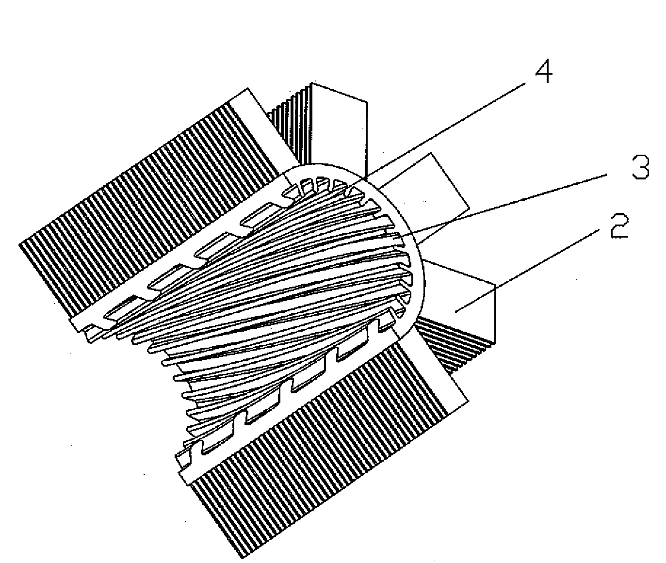
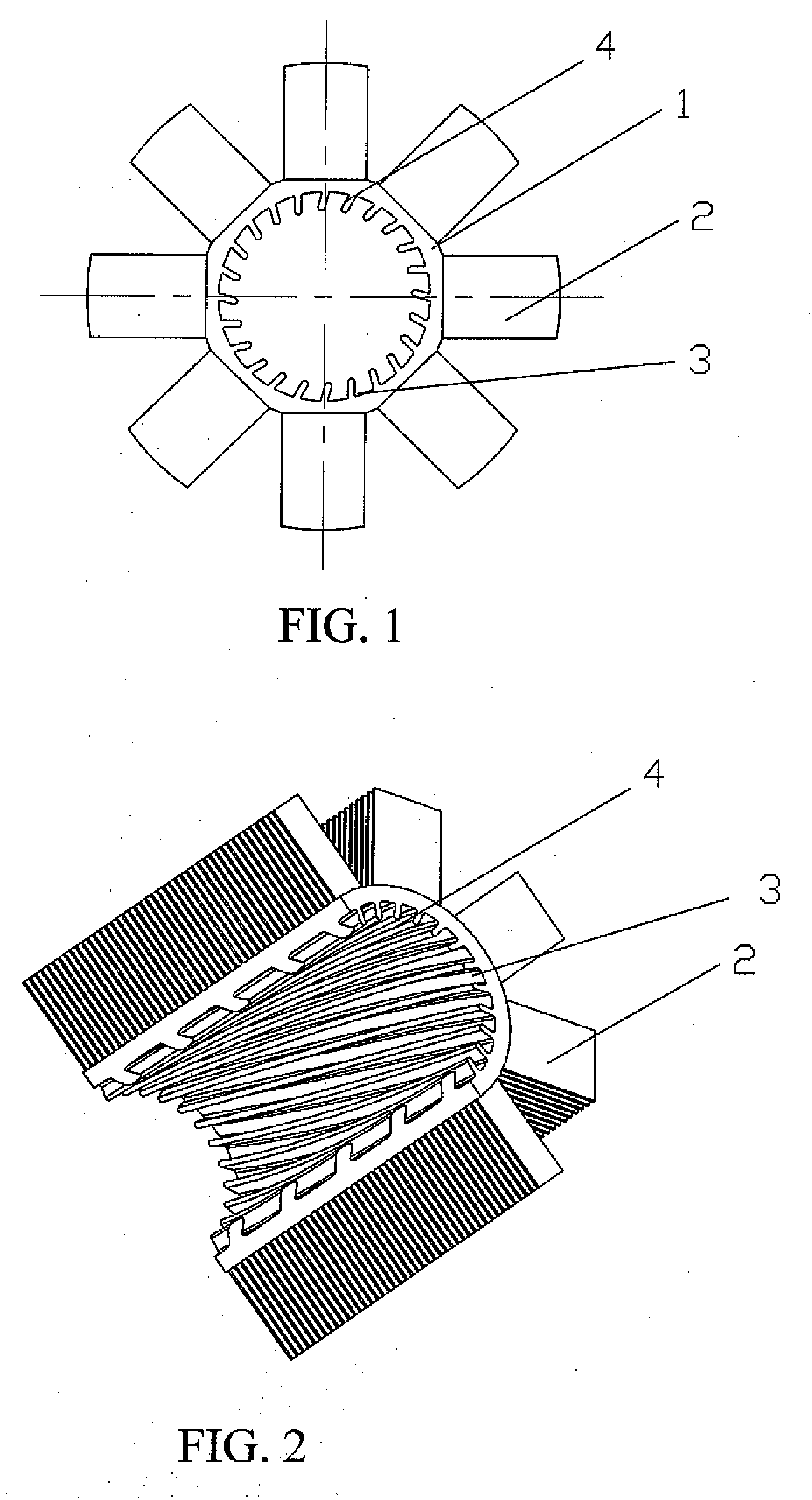
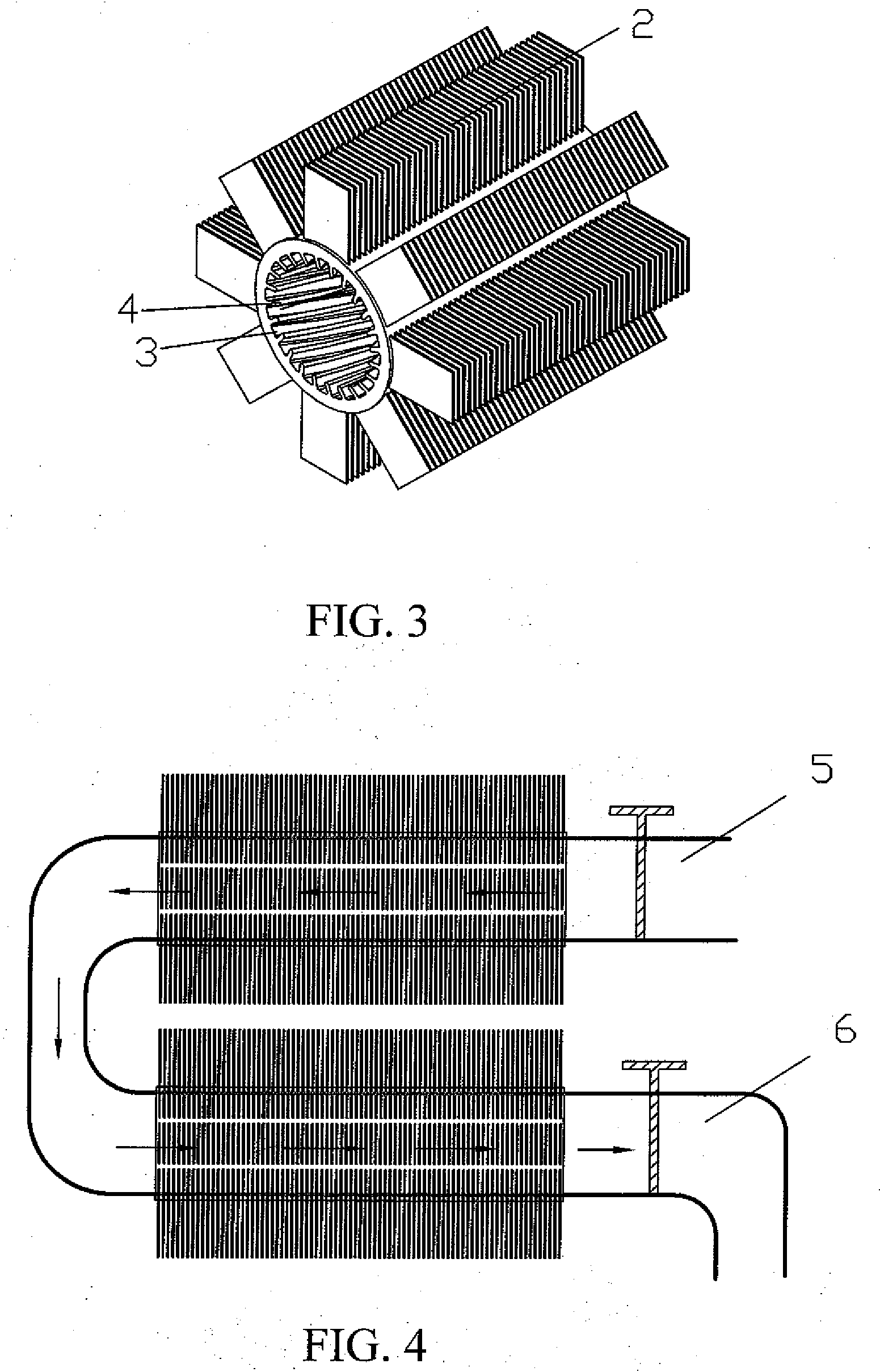
[0023]As shown in FIGS. 1-3, the heat exchanger tube of the present invention comprises a tube body 1, which includes an inside surface 3 exposed to a heating medium and an outside surface exposed to the air. The traversal cross section of the tube body could be in any suitable shape, such as a polygon, a circle, a rectangle and so on.

[0024]A plurality of lobes 2 are formed on the outside surface of the tube body 1 around the peripheral of the tube body 1. Preferably, each of the lobes 2 is formed along the whole length of the tube body 1. The lobes 2 could be formed by any means known in the related art. For example, the lobes 2 may be formed integrally with the tube body 1, or the lobes 2 could be formed by means of cutting the outside surface of the tube body 1. Preferably, the lobes 2 are systematical with respect to a longitude axis of the t...


PUM


Abstract

The present invention discloses a heat exchanger tube for a heating system, which is suitable for any kinds of heating systems mounted in doors. The heat exchanger tube comprises a tube body, in which a plurality of lobes are formed on an outside surface of the tube body around the peripheral of the tube body and a plurality of ribs are formed on an outside surface of the tube body along the length of the tube body. Each of the ribs is inclined with respect to the longitude axis of the tube body by an angle of about 15 degree. The advantages of the present invention are in that: 1. the ribs could increase the heat exchanging surface; 2. the lobes could increase the heat radiating surface; and 3. as the heat exchanger tube is made of aluminum or aluminum alloy, the heating medium would not be polluted by rust generated in iron tubes.

Description

CROSS-REFERENCE TO RELATED APPLICATION[0001]This application claims priority benefit of China patent application No. 200610122946.0 filed on Oct. 24, 2006, the contents of which are hereby incorporated by reference in its entirety.FIELD OF THE INVENTION[0002]The present invention relates to a heating system, in particular to heat exchanger tubes used in a heating system.BACKGROUND OF THE INVENTION[0003]In the world, there are many countries or regions located in the temperate zone or the frigid zone. In winter, the temperature in those countries or regions is too low to bear even in doors. Traditionally, heating systems is provided in buildings, to raise the temperature in the rooms. According to the source of heat, the heating systems could be classified into the following types.[0004](A) An electrical power 8 supplies electrical energy to a heating resistance 7, and the heated resistance warms the air, as shown in FIG. 5.[0005](B) Natural gas 9 is burned in a furnace, and the burn...

Claims


Application Information

Patent Timeline
Patent Type & Authority Applications(United States)
IPC IPC(8): F28F1/10
CPCF28D1/0477F28F1/04F28F1/26F28F21/084F28F1/42F28F1/422F28F1/40
Inventor CHEUNG, WAI KWAN
Owner CHEUNG WAI KWAN
Why Eureka
Try Eureka