Inverted electrical submersible pump completion to maintain fluid segregation and ensure motor cooling in dual-stream well

a technology of electrical submersible pumps and motor cooling, which is applied in the direction of fluid removal, earthwork drilling and mining, and wellbore/well accessories, etc. it can solve the problems of insufficient fluid flow through the motor in the inability of the inverted esp configuration to inherently allow the flow of fluids through the motor, and the electric motor used in such systems typically generates considerable heat. , to achieve the effect of less ancillary equipment requirements and better heat transfer characteristics

Inactive Publication Date: 2008-04-24
BAKER HUGHES INC
View PDF11 Cites 23 Cited by
  • Summary
  • Abstract
  • Description
  • Claims
  • Application Information

AI Technical Summary

Benefits of technology

[0008]A second embodiment involves the use of an inverted pump and a recirculation pump that are both located within a canister or pod. The recirculation pump circulates a portion of the produced water stream over the motor. One or more recirculation tubes may be employed to direct the water to a location proximate the motor of the ESP. A second portion of the water stream is injected back into the disposal zone. This embodiment is advantageous because it eliminates the necessity for a pack-off element within the canister and also because the embodiment utilizes water for cooling the motor flow rather than the oil-rich mixture. Water has better heat transfer characteristics than the oil-rich mixture. In this embodiment, the oil-rich mixture flows to the surface through a perforated joint that is run outside and above the pod / canister.
[0009]Another embodiment utilizes an inverted shroud within the canister / pod to force the water stream to flow passed the motor prior to entering the pump intake. An advantage to this design is that it is simple and has few ancillary equipment requirements.

Problems solved by technology

The electric motor used in such systems typically generates considerable heat.
Insufficient fluid velocity, however, will cause the motor to overheat and may lead to early motor failure.
However, an inverted ESP configuration does not inherently allow for a flow of fluids passed the motor when the ESP is located above well perforations.

Method used


Image

  • Inverted electrical submersible pump completion to maintain fluid segregation and ensure motor cooling in dual-stream well
  • Inverted electrical submersible pump completion to maintain fluid segregation and ensure motor cooling in dual-stream well
  • Inverted electrical submersible pump completion to maintain fluid segregation and ensure motor cooling in dual-stream well

Examples


Embodiment Construction

[0017]Before explaining the present invention in detail, it is important to understand that the invention is not limited in its application to the details of the embodiments and steps described herein. The invention is capable of other embodiments and of being practiced or carried out in a variety of ways. It is to be understood that the phraseology and terminology employed herein is for the purpose of description and not of limitation.

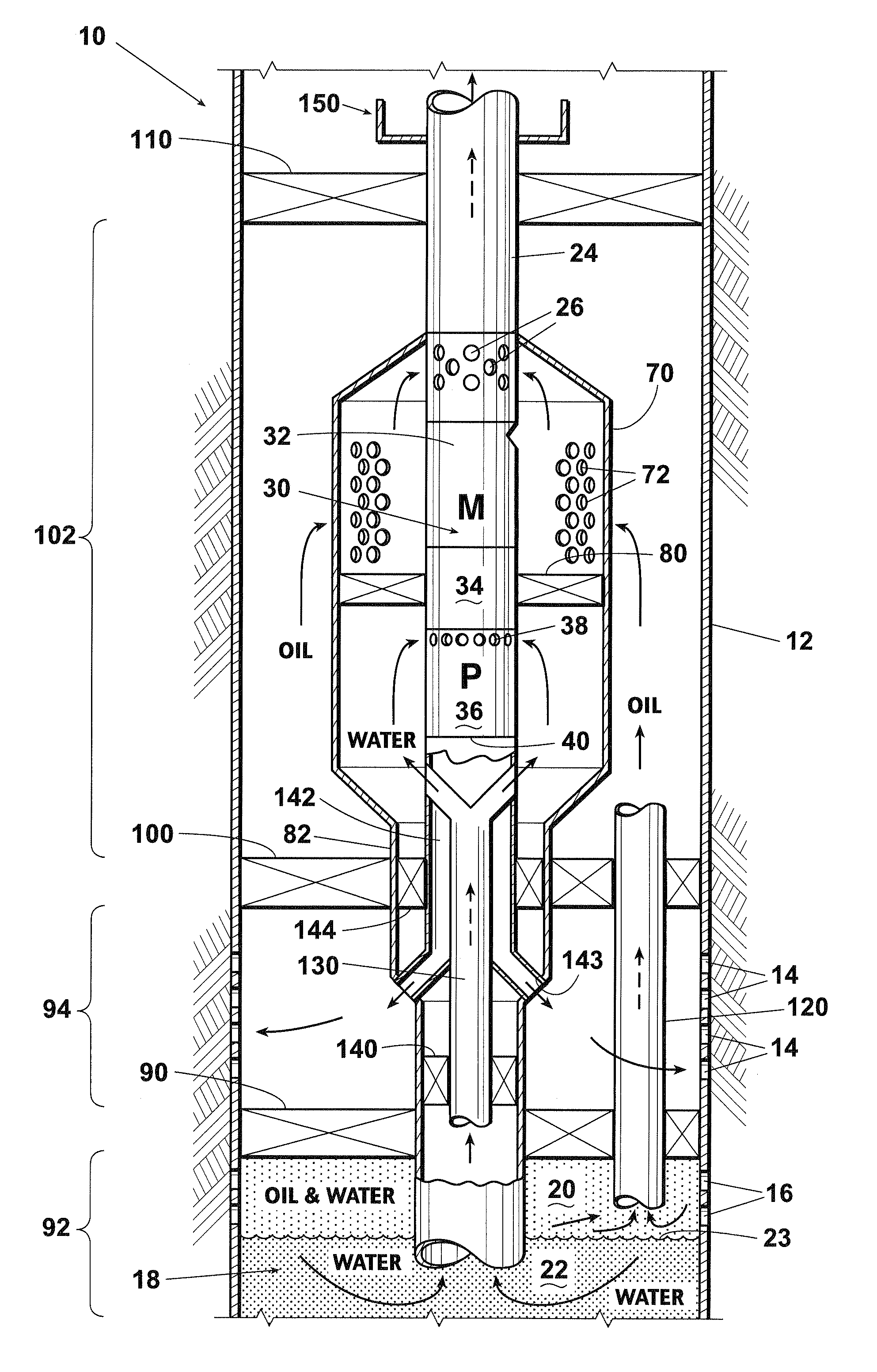
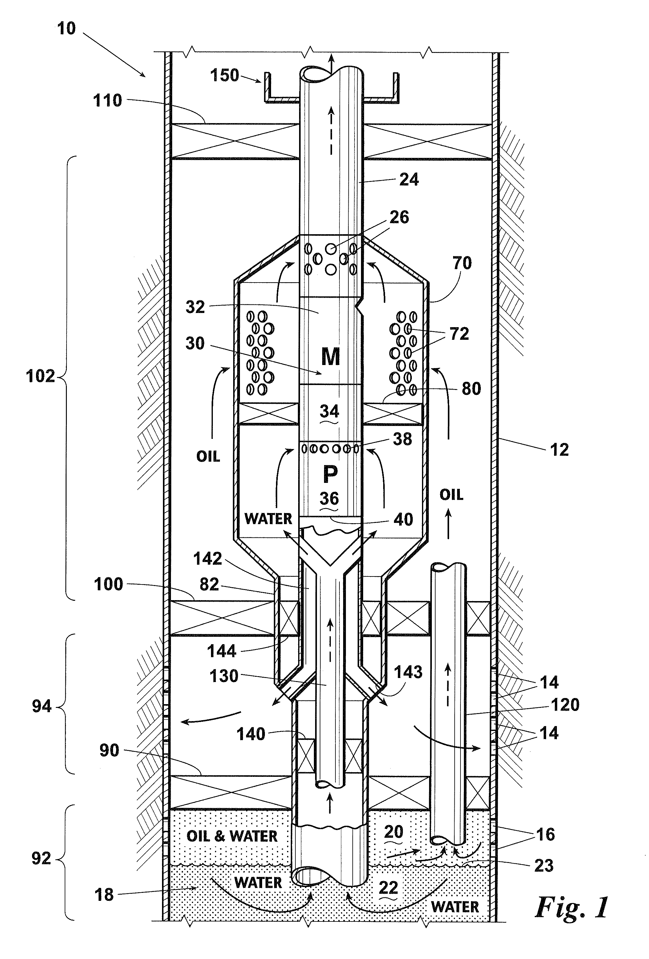
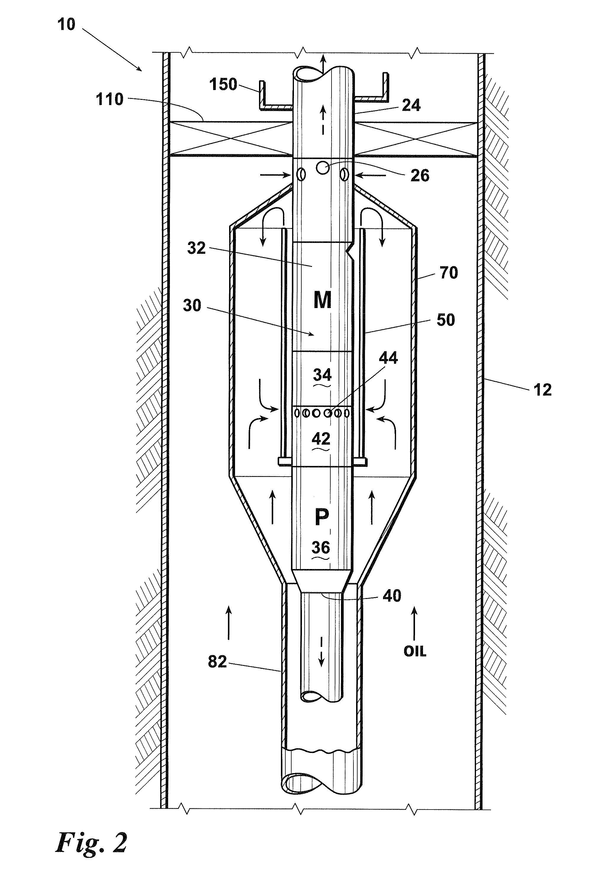
[0018]Referring now to FIGS. 1-5, shown are various embodiments of the inverted ESP completion of the invention for maintaining fluid segregation and to ensure motor cooling in a dual stream well. Well 10 has a well casing 12 that extends into the earth. Well casing 12 defines disposal perforations 14 (FIG. 1) and production perforations 16 (FIG. 1). Well fluids 18 (FIG. 1) migrate through production perforation 16 and accumulate in well casing 12. Well fluids 18 comprise an oil-rich mixture 20 and water 22. An oil / water interface 23 is defined there ...


PUM


Abstract

An electrical submersible pump (ESP) completion installed in casing perforated for water disposal and production. A packer separates the disposal zone and the production zone. An inverted ESP assembly is located inside of a canister. The ESP and canister are lowered on a tubing string into the casing. The canister has a downwardly extending canister extension flow-directing member that communicates with water in the casing and which passes through the disposal zone. Water is pumped down the canister extension member into the disposal zone and formation. Well fluids are drawn up the extension from the production zone. Various configurations are disclosed to facilitate flowing well fluids, e.g., oil-rich mixture or water passed the motor for cooling the motor of the inverted ESP while maintaining fluid segregation. The completion is particularly suited for production wells wherein the oil and water have a strong tendency to naturally segregate within the wellbore.

Description

CROSS REFERENCE TO RELATED APPLICATIONS[0001]This application claims the benefit of co-pending U.S. patent application Ser. No. 11 / 583,692, filed Oct. 19, 2006, entitled “Inverted Electrical Submersible Pump Completion to Maintain Fluid Segregation and Ensure Motor Cooling in Dual Stream Well,” which application is incorporated herein by reference.FIELD OF THE INVENTION[0002]This invention relates generally to an electrical submersible pump (ESP) completion that maintains fluid segregation and ensures motor cooling in a dual stream well, i.e., in a well that exhibits a considerable degree of natural oil / water fluid segregation within the wellbore. More particularly, the invention relates to an inverted ESP deployed within a canister, wherein produced well fluids are directed passed the motor for cooling, an oil-rich production mixture is delivered to the surface and produced and water is re-injected in-situ into a separate injection zone.BACKGROUND OF THE INVENTION[0003]Fluid in man...

Claims


Application Information

Patent Timeline
Patent Type & Authority Applications(United States)
IPC IPC(8): E21B43/00
CPCE21B43/38E21B43/128E21B43/385
Inventor KNIGHT, JEFFREY W.THOMPSON, HOWARD G.VILCINSKAS, ERNESTO ALEJANDRO
Owner BAKER HUGHES INC
Why Eureka
Try Eureka