Smooth non-linear springs, particularly smooth progressive rate steel springs, progressive rate vehicle suspensions and method

a non-linear spring and progressive rate technology, applied in the direction of spring/damper functional characteristics, spring/damper design characteristics, resilient suspensions, etc., can solve the problems of perishable cam mechanism, inferior steel springs in many aspects such as strength, durability, reliability and cost, and usually feature inferior non-differentiable damping characteristics

Inactive Publication Date: 2008-04-24
OLEDZKI WIESLAW JULIAN
View PDF21 Cites 8 Cited by
  • Summary
  • Abstract
  • Description
  • Claims
  • Application Information

AI Technical Summary

Benefits of technology

[0015]It is therefore an object of the present invention to provide lightweight springs made of elastic material, particularly steel s...

Problems solved by technology

However, these suspensions are inferior to steel ones in many aspects such as strength, durability, reliability and cost, and their damping characteristic, being determined by the thermodynamic properties (adiabatic exponent) of the gas (air or nitrogen) they utilize, cannot be freely adjusted and is far from optimum.
There are also some progressive rate vehicle suspensions fitted with steel springs, but they usually feature inferior non-differentiable damping characteristic.
This is due to the fact that those suspensions used unreliable and perishable cam mechanisms to achieve required non-linearity of damping characteristic.
Some non-linear (progressive) rate steel springs, e.g. coil and leaf springs, are well known from the prior art, however these springs are far from being completely satisfactory.
This assures only unsatisfactory discrete (approximately) change of the spring rate.
This method also provides springs with unsatisfactory characteristic, which is not differentiable (essentially, t...

Method used


Image

  • Smooth non-linear springs, particularly smooth progressive rate steel springs, progressive rate vehicle suspensions and method
  • Smooth non-linear springs, particularly smooth progressive rate steel springs, progressive rate vehicle suspensions and method
  • Smooth non-linear springs, particularly smooth progressive rate steel springs, progressive rate vehicle suspensions and method

Examples


example 1

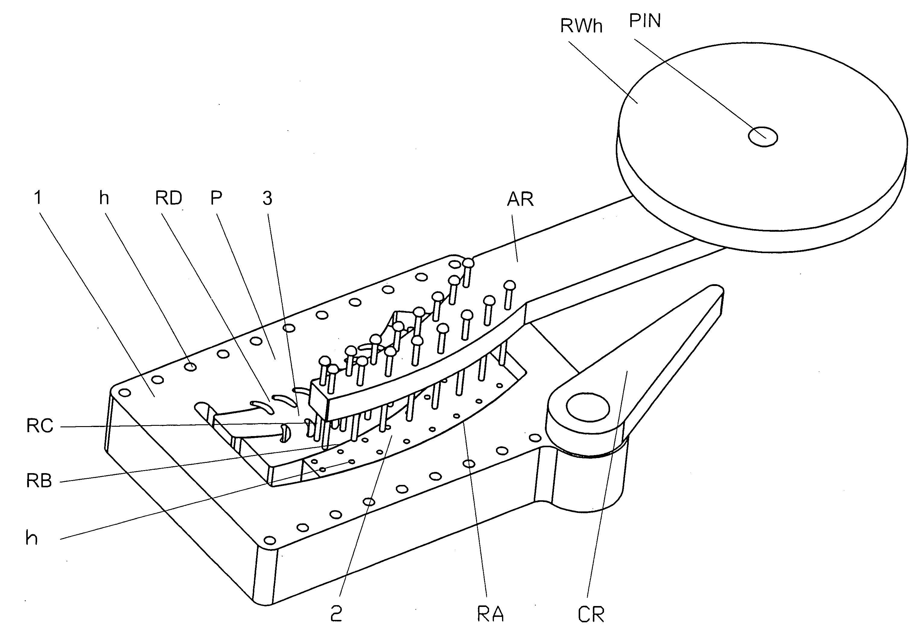
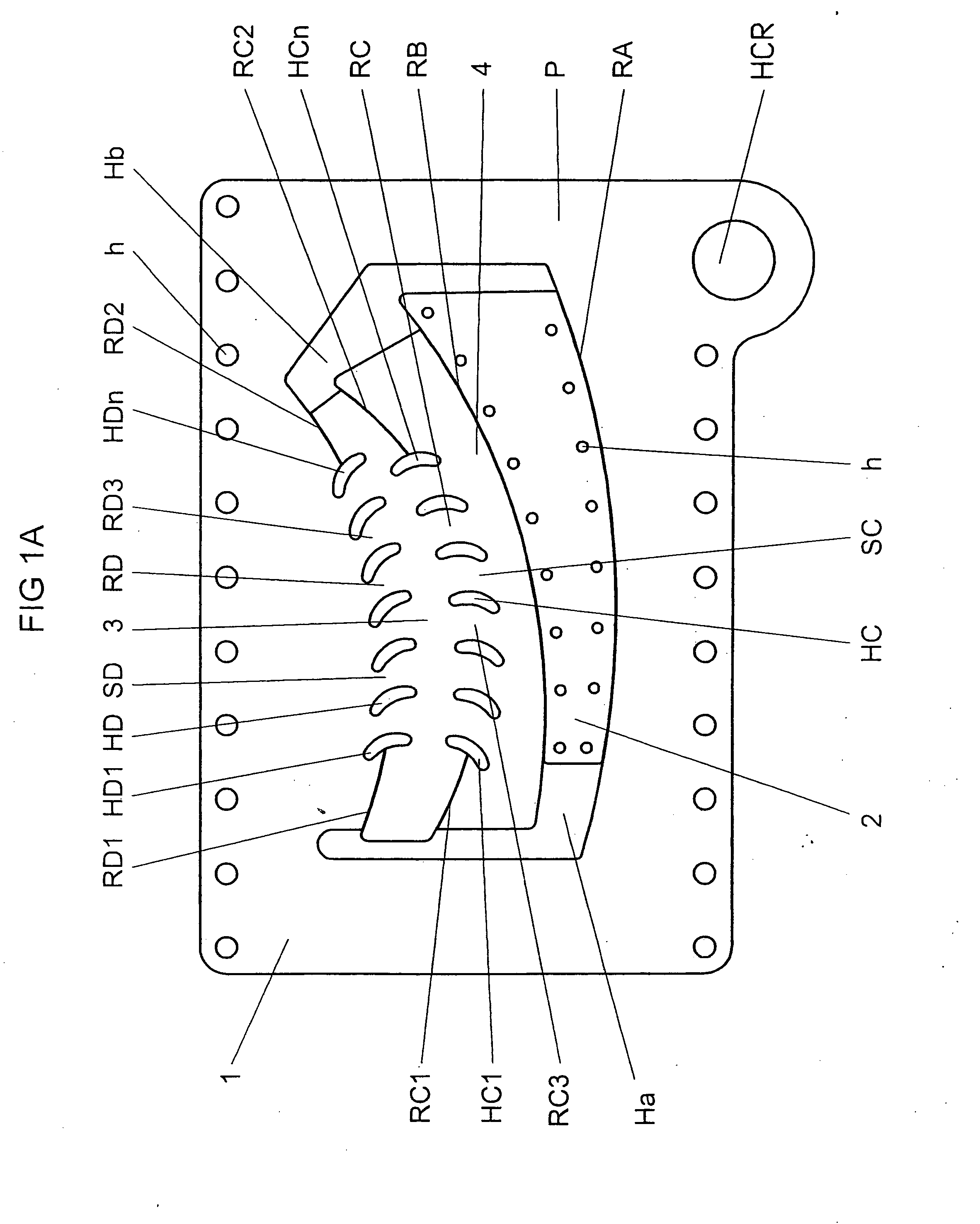
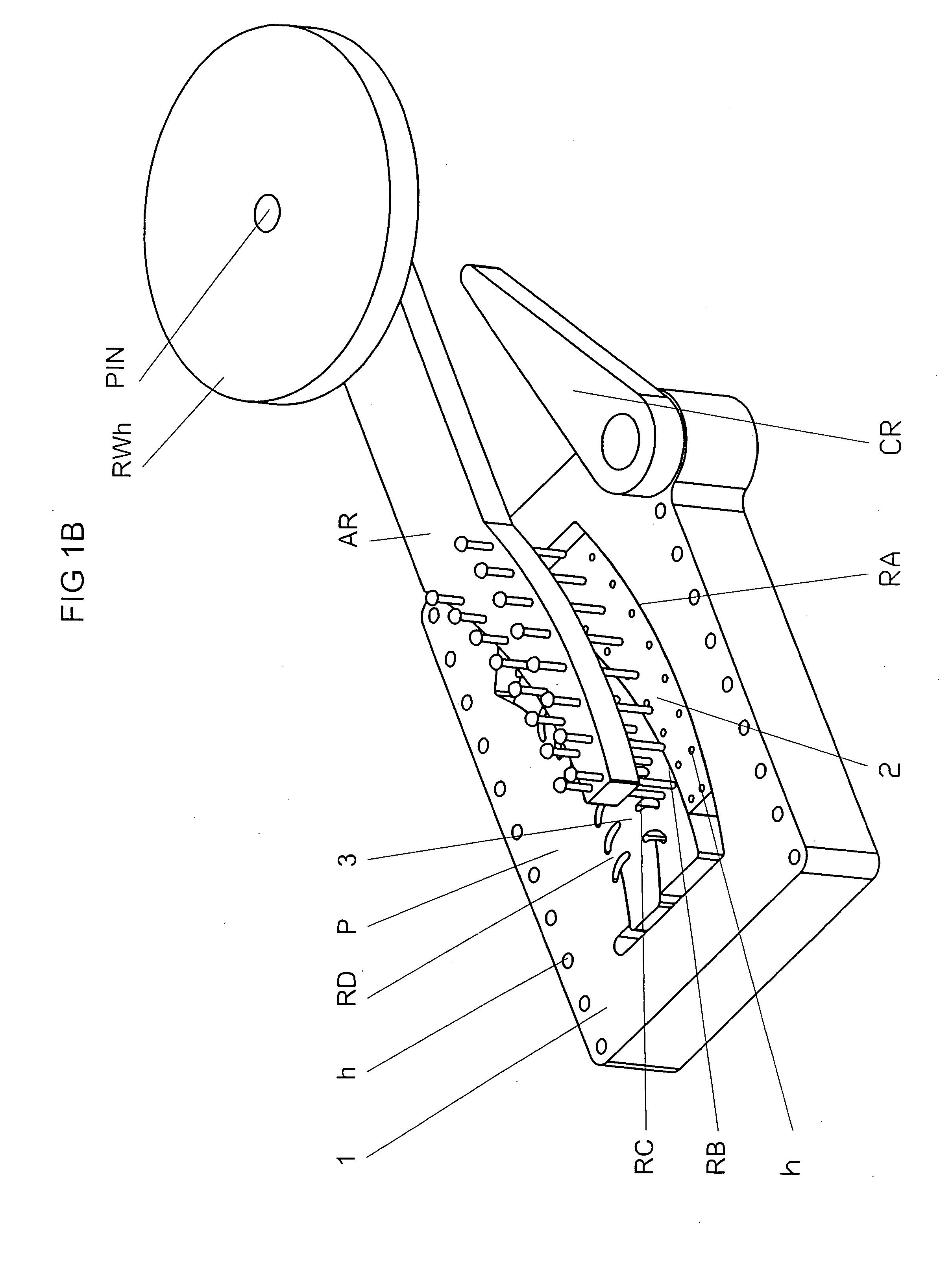
[0114]Referring to FIGS. 1A-1D there is shown a smooth progressive rate spring (S) obtained by applying Main Procedure as described in section Summary of the Invention and a complete vehicle suspension unit utilizing this spring, both in accordance with the present invention.

[0115]Now, referring to FIGS. 1A and 1D, four points (A), (B), (C) and (D) are fixed in the plane of the steel plate (P) (made of spring steel), and four circular arcs (LA), (LB), (LC) and (LD) with the center at the points (A), (B), (C) and (D) respectively are traced in the plate (P) (see FIG. 1D). Four regions (RA), (RB), (RC) and (RD) of decreased stiffness are formed in the plate (P). The regions (RA), (RB), (RC) and (RD) assume general form of the circular arc (LA), (LB), (LC) and (LD) respectively.

[0116]To be more precise, the region (RA) (of zero stiffness; in other words the elasticity coefficient of this region equals zero) is obtained by cutting the plate (P) precisely along the arc (LA).

[0117]Similar...

example 2

[0128]FIGS. 2A-2F shows the spring substantially of the type depicted in FIGS. 1A-1D with an alternative form of the regions (RA), (RB), (RC) and (RD) with decreased stiffness. The description above applies almost literally to this spring with only minor changes.

[0129]Thus the four points (A), (B), (C) and (D) are fixed in the plane of the steel plate (P) (made of spring steel), and four circular arcs (LA), (LB), (LC) and (LD) with the center at the points (A), (B), (C) and (D) respectively are traced in the plate (P). (These two operations are completely analogous to these of Example 1, and therefore the points (A), (B), (C) and (D) and the arcs (LA), (LB), (LC) and (LD) are not shown in the accompanying FIGS. 2A-2F). Four regions (RA), (RB), (RC) and (RD) of decreased stiffness are formed in the plate (P). The regions (RA), (RB), (RC) and (RD) assume general form of the circular arc (LA), (LB), (LC) and (LD) respectively.

[0130]To be more precise, all the regions (RA), (RB), (RC) a...

example 3

[0140]Referring to FIGS. 3A-3C there is shown another smooth progressive rate spring (S) obtained by applying Main Procedure as described above and a complete vehicle suspension unit utilizing this spring in accordance with the present invention.

[0141]Unlike the springs of Examples 1 and 2, this spring is formed using two plates (PA) and (PZ) made of spring steel. Both the plates (PA) and (PZ), of the same dimensions and structure, have substantially circular parts (in which regions of decreased stiffness are formed) and elongated parts intended to form the integral road wheel arm; this structure of the plates allows for further decreasing weight and dimensions of the complete suspension unit. This example is also intended to illustrate the method of introducing in the spring some initial internal stresses.

[0142]Two points (A) and (B) are fixed in the plane of the steel plate (PA), and two circles (LC) and (LB) with the center at the points (A) and (B) respectively are traced in the...


PUM


Abstract

The invention solves the problem of designing and manufacturing springs made of elastic materials, particularly steel springs, with prescribed characteristic (dependence of flex on external load) given by a smooth (i.e. differentiable) non-linear function. The method according to the invention consists in forming an elastic body with suitably shaped regions of diversified stiffness and (possibly) diversified initial internal stresses (this suitable shape of the regions lies at the hart of the invention and is covered by separate patent claims).

Description

TECHNICAL FIELD OF THE INVENTION[0001]The present invention relates to springs and vehicle suspensions, particularly steel springs and suspensions, and is particularly concerned with the problem of obtaining steel springs with differentiable non-linear (progressive) spring rate and vehicle suspensions with optimal damping characteristic. The invention provides springs (particularly steel springs) with highly non-linear differentiable characteristic (dependence of the spring force on the external load), in particular progressive rate steel springs (steel springs the stiffness (spring “constant”) of which rises as the external load of the spring rises). The invention also provides a method of producing steel springs with progressive spring rate as well as complete vehicle suspension units utilizing such springs.STATE OF THE ART AND BACKGROUND OF THE INVENTION[0002]It is well known that progressiveness of the damping characteristic of vehicle suspension is a highly desirable feature th...

Claims


Application Information

Patent Timeline
IPC IPC(8): F16F7/00
CPCB60G11/00F16F1/025F16F2230/36F16F2228/06F16F1/377
Inventor OLEDZKI, WIESLAW JULIAN
Owner OLEDZKI WIESLAW JULIAN
Why Eureka
Try Eureka