Arrangement for fastening permanent magnets to rapidly rotating rotors of electric machines

Active Publication Date: 2008-04-24
JENOPTIK ADVANCED SYST GMBH
View PDF10 Cites 55 Cited by
  • Summary
  • Abstract
  • Description
  • Claims
  • Application Information

AI Technical Summary

Benefits of technology

[0009]It is the primary object of the invention to find a novel possibility for fastening permanent magnets to the rotor of rapidly rotating electric machines which allows a reliable fastening of the permanent magnets for high rotating speeds and high temperature loads under confined spatial conditions without requirin

Problems solved by technology

This method is limited as far as its possible uses because of the limiting holding power of adhesives at elevated temperatures and large centrifugal forces due to high rotating speeds.
This method can only be applied in certain mechanical and magnetic designs and reduces the magnetic exploitation of the system.
While wrappings of electrically conductive material usually have the disadvantage that the rotor parts are additionally heated because of the f

Method used


Image

  • Arrangement for fastening permanent magnets to rapidly rotating rotors of electric machines
  • Arrangement for fastening permanent magnets to rapidly rotating rotors of electric machines
  • Arrangement for fastening permanent magnets to rapidly rotating rotors of electric machines

Examples


Embodiment Construction

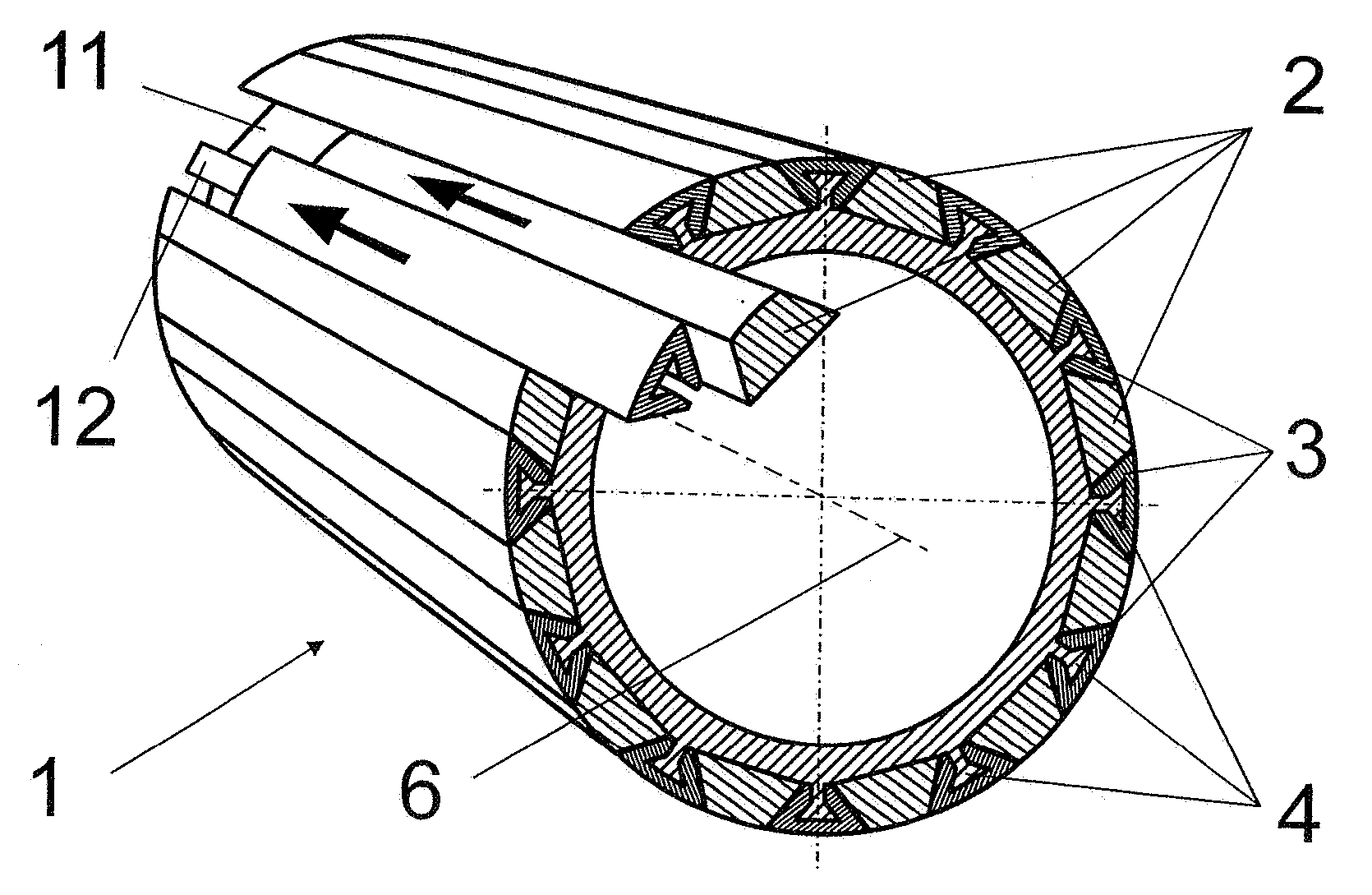
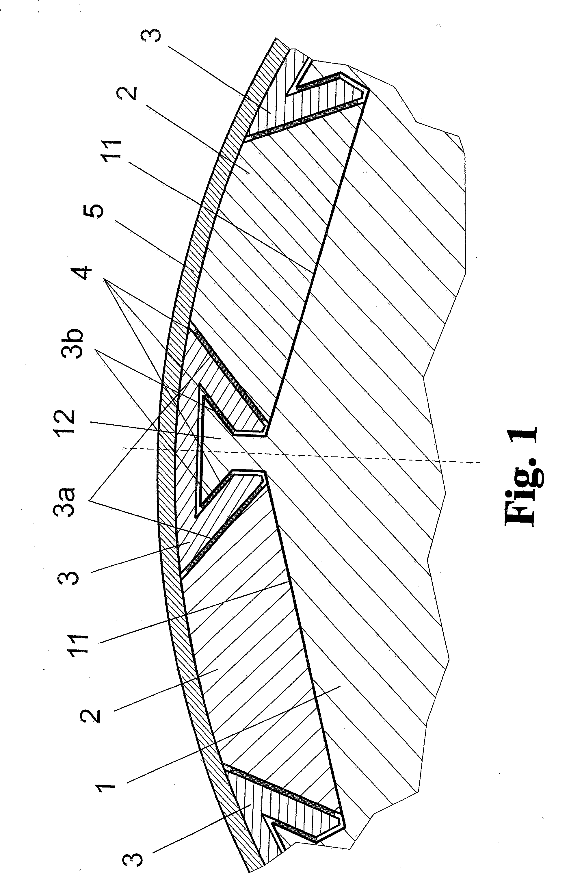
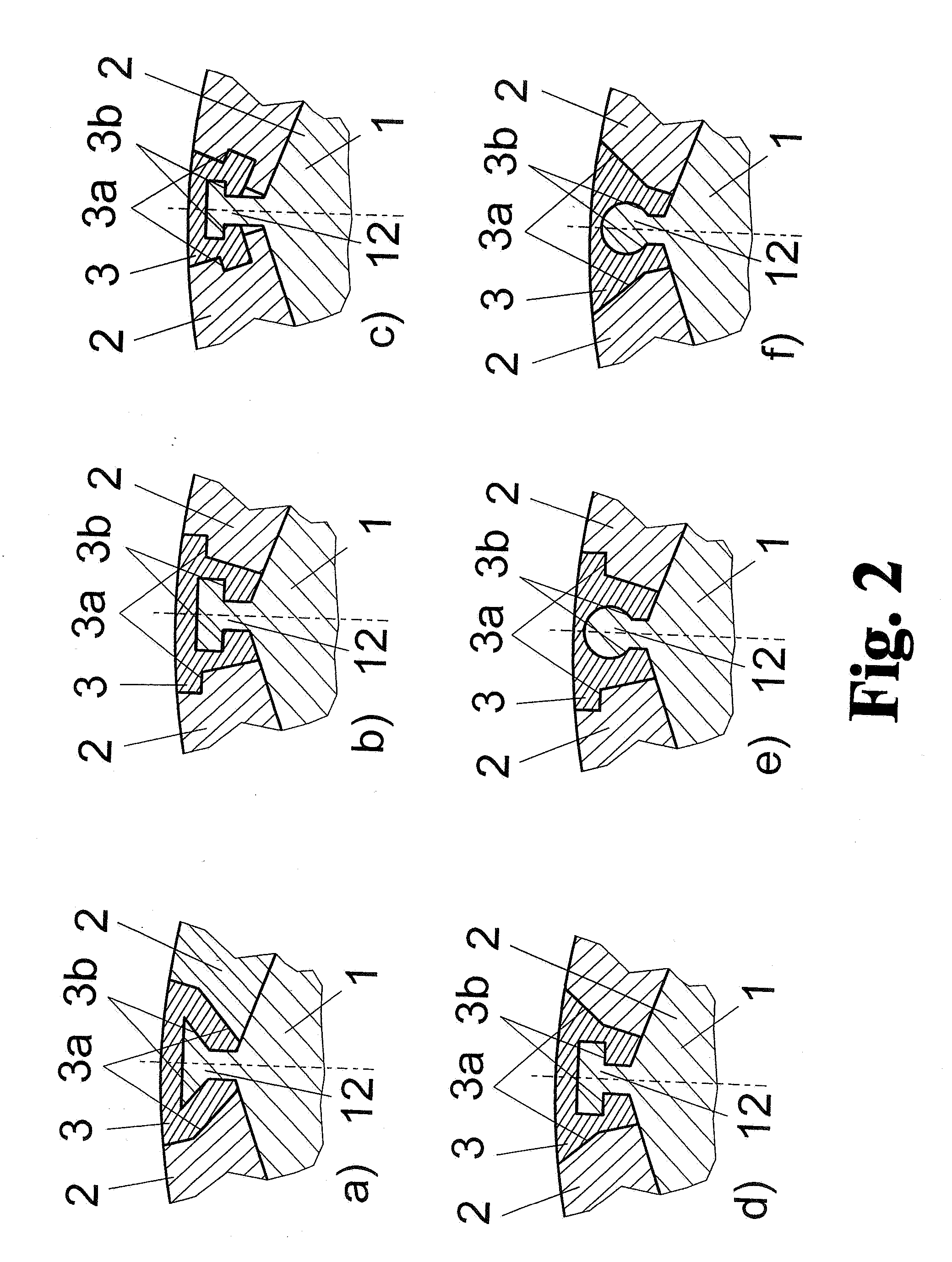
[0033]As is shown by FIG. 1 viewed together with FIG. 5, the invention basically comprises a rotor 1 which is shaped as a cylindrical body, longitudinally oriented permanent magnets 2 being arranged so as to be evenly distributed at its periphery and fastened to the rotor 1 by profile parts 3 which are arranged therebetween so as to engage radially in a claw-like or wedge-shaped manner and which have contact surfaces 3a and 3b that diverge symmetrically in pairs. The profile parts 3 hold the permanent magnets 2 by means of contact surfaces 3a which diverge in pairs outward viewed in radial direction, and the profile parts 3 themselves are likewise secured against radial forces by positive engagement by contact surfaces 3a at the rotor 1 which diverge in pairs at the sides of rotor grooves 11 or rotor webs 12 arranged therebetween.

[0034]The profiles which are defined in this way are adapted to one another, i.e., the shapes of the sides of the rotor grooves 11 or rotor webs 12 and of ...


PUM


Abstract

The invention is directed to an arrangement for fastening permanent magnets to rapidly rotating rotors of electric machines. It is the object of the invention to find a novel possibility for fastening permanent magnets to the rotor of rapidly rotating electric machines which allows the magnets to be fixed so as to be secure against centrifugal forces for high rotating speeds and under confined spatial conditions without a frictionally engaging connection of magnet holders to the rotor. According to the invention, this object is met with a plurality of permanent magnets which are arranged at the outer circumference of the rotor with profile parts which are arranged alternately therebetween in that coaxially extending rotor grooves are introduced in the outer surface of the rotor, the sides of the rotor grooves having contact surfaces which at least partially converge outward with respect to radial direction for contact surfaces of the profile parts which diverge in a conforming manner, and the profile parts are shaped in such a way that they retain the permanent magnets pairwise in a claw-like manner in a positive engagement against radial forces of the rotor rotation. Gaps which inevitably remain at the contact surfaces for reasons of manufacture are filled with a liquid, hardenable medium

Description

CROSS-REFERENCE TO RELATED APPLICATIONS[0001]This application claims priority of German Application No. 10 2006 049 825.9, filed Oct. 21, 2006, the complete disclosure of which is hereby incorporated by reference.BACKGROUND OF THE INVENTION[0002]a) Field of the Invention[0003]The invention is directed to an arrangement for fastening permanent magnets to rapidly rotating rotors of electric machines. It is preferably applied in cases of special demands on mechanical strength at high peripheral speeds and high operating temperatures and suppression of eddy currents.[0004]b) Description of the Related Art[0005]Arrangements in which the magnets are fastened to a magnetizable rotor support by means of a glue and are fixed in place by a nonmagnetic wrapping are known in the prior art. This method is limited as far as its possible uses because of the limiting holding power of adhesives at elevated temperatures and large centrifugal forces due to high rotating speeds.[0006]In another solutio...

Claims


Application Information

Patent Timeline
IPC IPC(8): H02K1/28H02K1/27
CPCH02K1/28H02K1/278
Inventor GRUENHAGEN, THOMAS
Owner JENOPTIK ADVANCED SYST GMBH
Why Eureka
Try Eureka