
Patient monitor using radio frequency identification tags

a radio frequency identification and patient monitor technology, applied in the field of radio frequency identification tags, can solve the problems of recording loss or damage, other medical workers must utilize a limited amount of resources, and other problems, to achieve the effect of reducing drawbacks and transporting patients with less risk

Inactive Publication Date: 2008-04-24
MASIMO CORP
View PDF99 Cites 263 Cited by
  • Summary
  • Abstract
  • Description
  • Claims
  • Application Information

AI Technical Summary

Benefits of technology

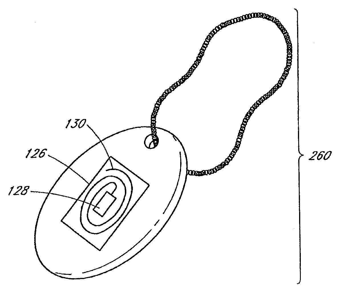
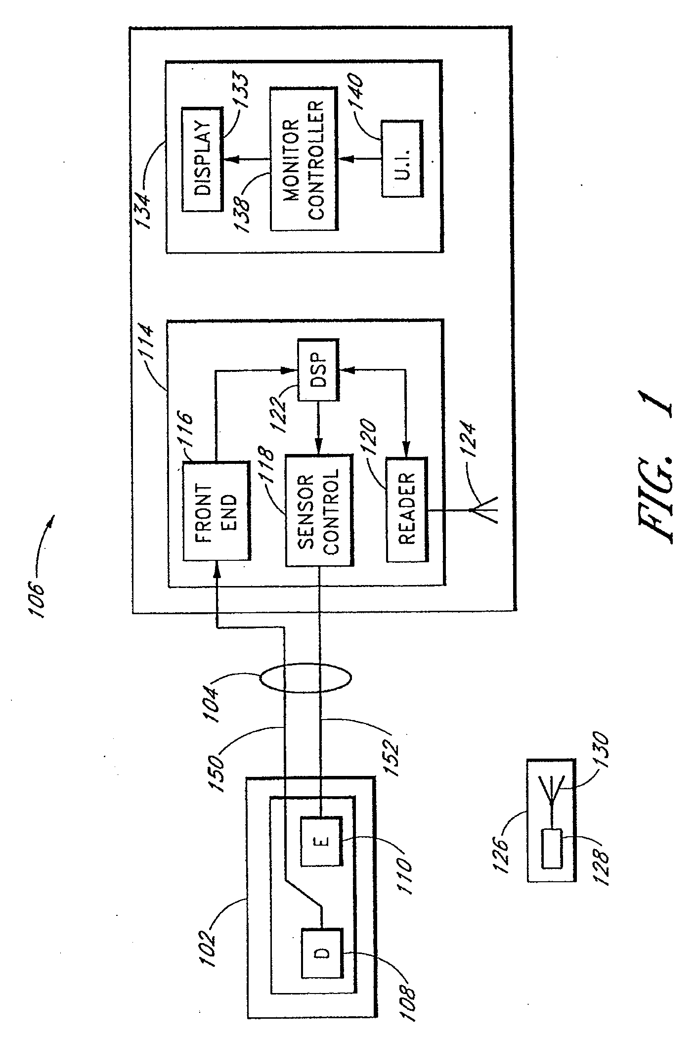
[0013] An embodiment of this disclosure also provides a RFID reader that can wirelessly retrieve the information stored on the RFID tag and display the retrieved data utilizing a stripped down or partial patient monitor.
[0015] A further advantage of an embodiment of this disclosure includes the ability to store acquired patient identification data on the RFID tag, thereby advantageously allowing caregivers or others to find specific individuals, ensure that the tags are associated with the correct patients, or the like.

Problems solved by technology

In these situations, doctors and other medical workers must utilize a limited amount of resources to assess, track, manage, and treat as many patients as possible.
However, there are drawbacks associated with this method of triage.
For example, recordings can get lost or damaged in the confusion of the situation or during movement of a patient from one location to another.
Such drawbacks often create a need to duplicate previously taken readings and loses at least some trending data that otherwise may have been available.
While implementation of an automatic update may prevent human error in recording readings, smart cards are still not ideal for triage of mass casualty situations.
Smart cards can be easily lost, dropped, or misplaced in the confusion of disaster relief and patient transport.
Such contacts are susceptible to spoilage from dirt and damage.

Method used


Image

  • Patient monitor using radio frequency identification tags
  • Patient monitor using radio frequency identification tags
  • Patient monitor using radio frequency identification tags

Examples


Embodiment Construction

[0023] A patient monitor, such as a pulse oximeter, generally comprises a sensor component and a processing component that processes signals received from the sensor component. In an embodiment, the monitor displays physiological data in some format, such as on an electronic display. In situations when it is impossible or impractical to utilize a patient monitor to monitor one patient. It is advantageous to store patient data and / or some or all sensor data, processed data, trend data, encoded data of any or all of the foregoing, or the like for later reading or updating. Accordingly, an embodiment of the disclosure comprises a patient monitoring system including a sensor, a processing unit, and the RFID tag. The RFID tag comprises an information element, such as an integrated circuit, coupled with an antenna. In an embodiment, the processing unit communicates with an antenna capable of broadcasting and / or receiving electromagnetic signals. The patient monitoring system may broadcast...


PUM


Abstract

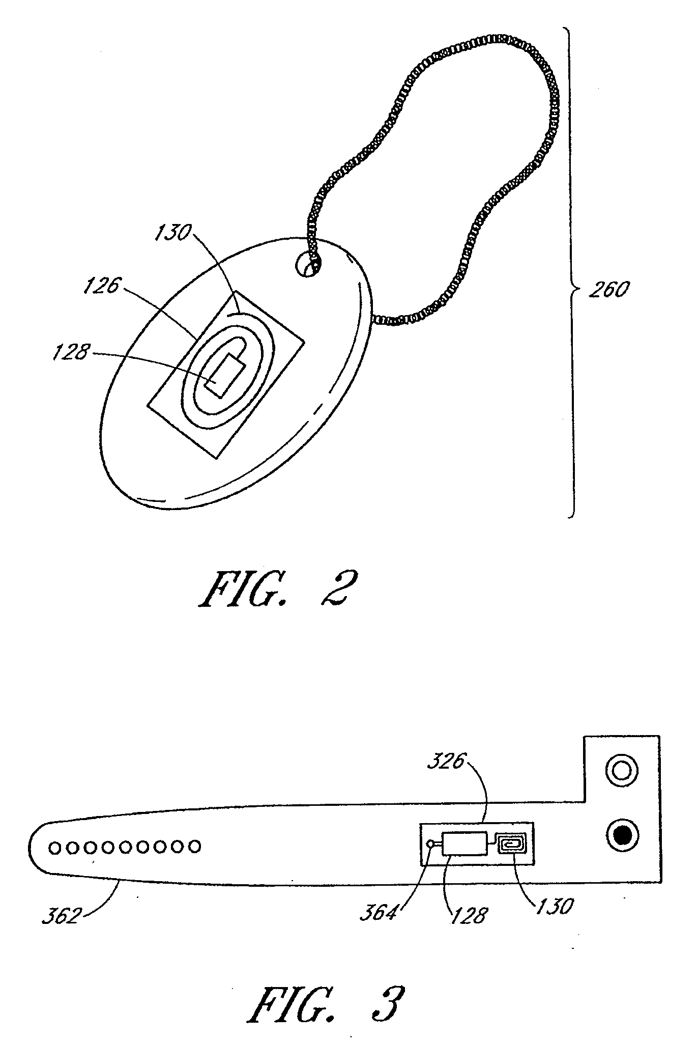
One aspect of the disclosure is to provide a patient monitoring system including a radio frequency identification (RFID) tag. The system comprises a patient monitor capable of communicating with the RFID tag. The RFID tag may advantageously store information useful in hospital environments, triage or disaster environments, home care environments, or the like. In some embodiments, the RFID tags may be provided as parts of wrist bands, dog tags, disposable sensor components, sensors or the like that are left with a patient.

Description

PRIORITY CLAIM [0001] This application claims priority to U.S. Provisional Application No. 60 / 851,160, titled “Patient Monitor Using Radio Frequency Identification Tags” and filed on Oct. 12, 2006, the disclosure of which is incorporated herein by reference.BACKGROUND [0002] 1. Field of the Disclosure [0003] The present disclosure relates in general to the use of radio frequency tags and more specifically to their use in patient monitors, such as oximeter systems. [0004] 2. Description of the Related Art [0005] Quick diagnoses and efficient care for patients in trauma situations are often key to the survival of those patients. Perhaps, nowhere is this more clear than in large scale triage scenarios, such as can be brought about by natural disasters, industrial accidents, terrorist attacks, and wars. In these situations, doctors and other medical workers must utilize a limited amount of resources to assess, track, manage, and treat as many patients as possible. One important key to s...

Claims


Application Information

Patent Timeline
IPC IPC(8): G08B23/00
CPCA61B5/0002A61B5/0026A61B5/145A61B5/681A61B2019/448G06F19/3418A61B2560/0412A61B2562/08A61B2562/164G06F19/323A61B2560/0214A61B90/98G16H10/65G16H40/67
Inventor WELCH, JAMES P.MASON, GENEKIANI, MASSI E.
Owner MASIMO CORP
Learn More