Scattered pilot location detector

a detector and pilot technology, applied in the direction of polarisation/directional diversity, broadcast system receiving, transmission path division, etc., can solve problems such as the risk of degrading a synchronous characteristi

Active Publication Date: 2008-04-24
LAPIS SEMICON CO LTD
View PDF3 Cites 88 Cited by
  • Summary
  • Abstract
  • Description
  • Claims
  • Application Information

AI Technical Summary

Benefits of technology

[0014]In the present invention, each of the results of multiplication obtained by multiplying received signals by a pseudo random bit sequence is inputted to N arithmetic circuits. The respective arithmetic circuits respectively extract pilot symbols in accordance with their corresponding patterns and calculate sums of phase differences between the extracted pilot symbols, whereby the corresponding arithmetic circuit maximum in the calculated sum is detected from within these N arithmetic circuits. Thus, an advantageous effect is brought about in that patterns of SP symbols can be detected based on received signals corresponding to one symbol period without using a TMCC signal.

Problems solved by technology

(1) While there is a need to establish the synchronism of the OFDM frame for the purpose of detecting each pattern of the SP symbols, the corresponding synchronous symbol in the TMCC signal must be detected to establish the synchronism of the OFDM frame. It is therefore necessary to receive 16 symbols or more corresponding to a synchronous symbol length for synchronous establishment.
(2) Since the TMCC signal is modulated based on the DBPSK system, there is a need to perform differential demodulation for its reception and there is hence a risk of degrading a synchronous characteristic.

Method used


Image

  • Scattered pilot location detector
  • Scattered pilot location detector
  • Scattered pilot location detector

Examples


first preferred embodiment

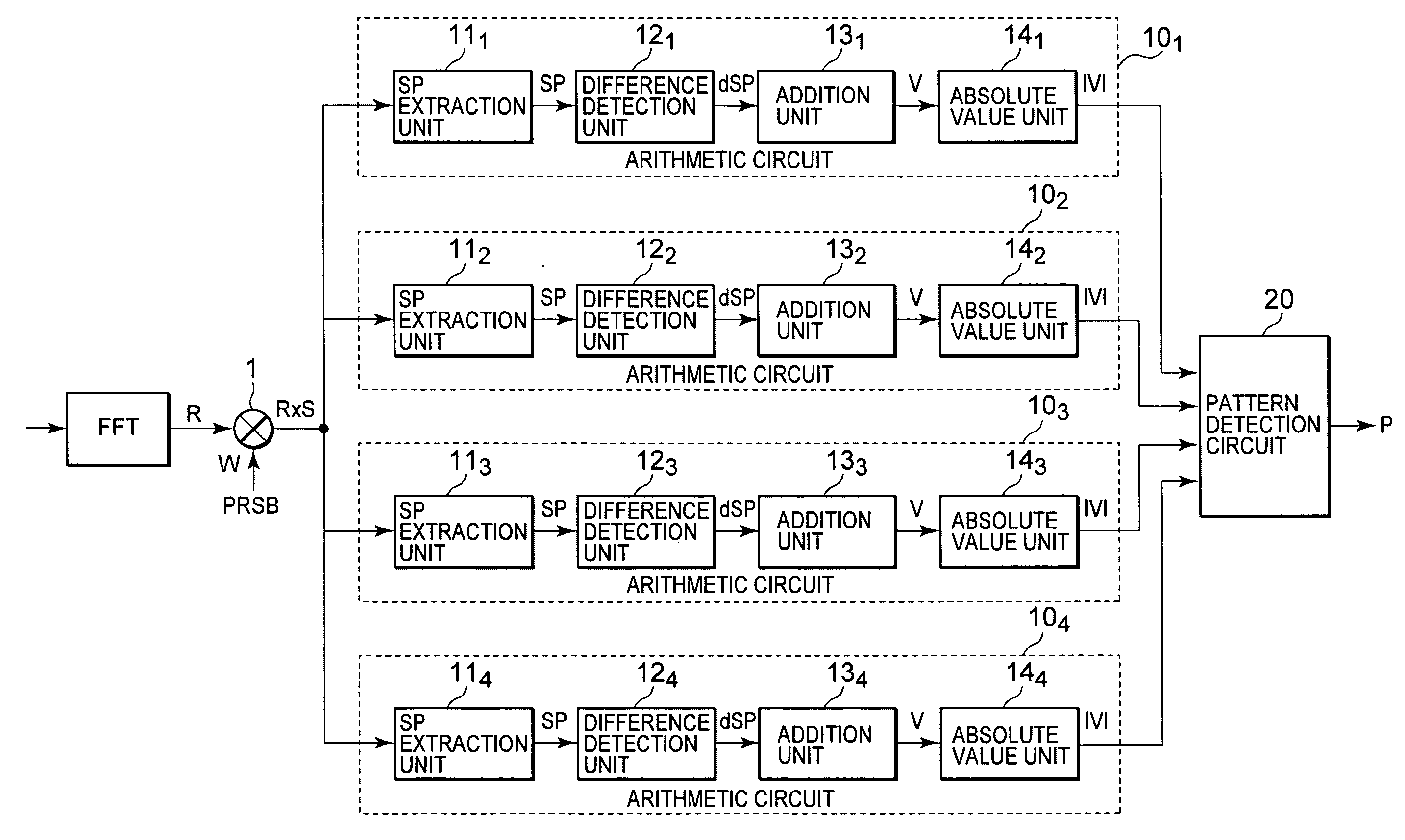
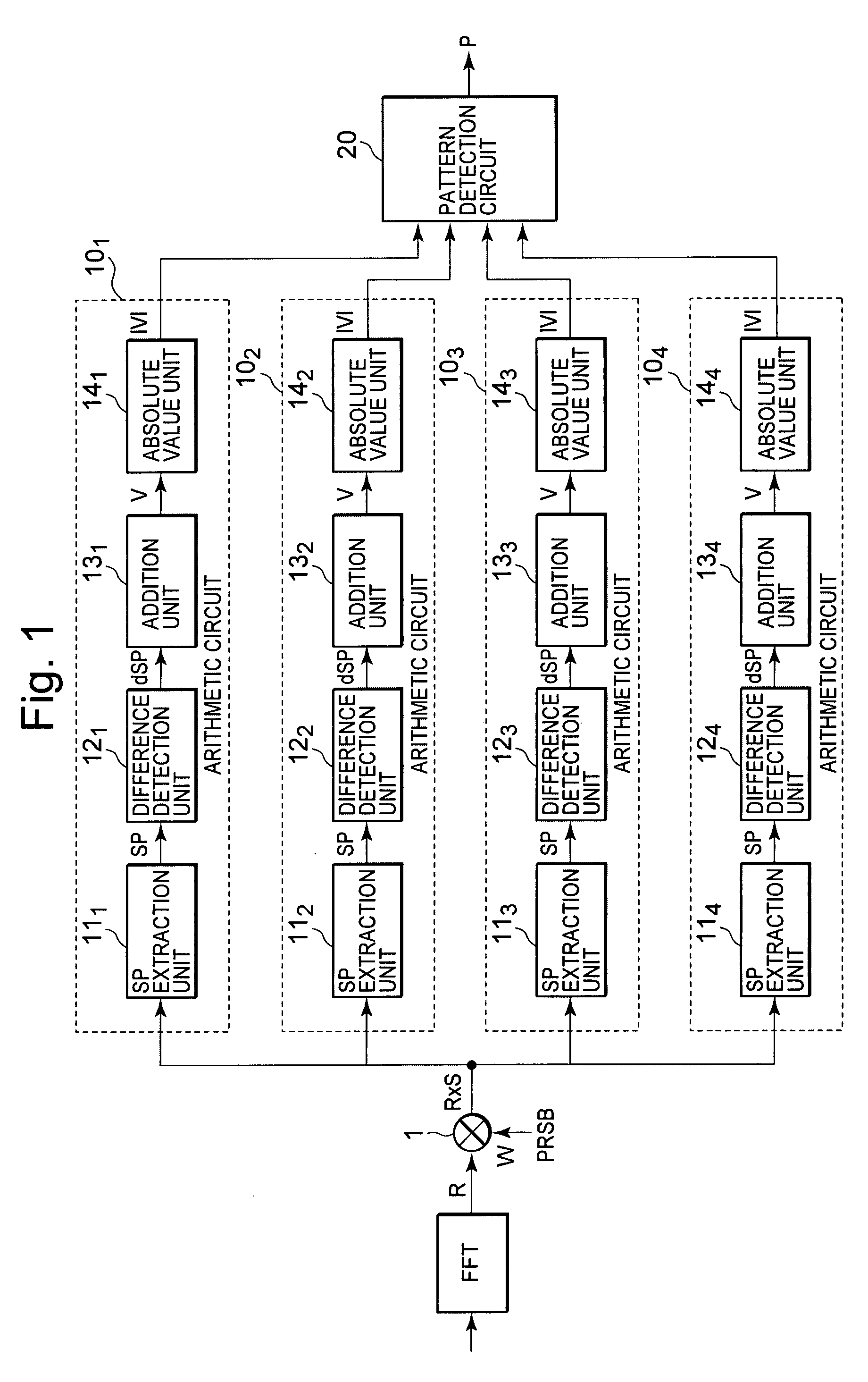
[0022]FIG. 1 is a configuration diagram of an SP layout or location detector showing a first embodiment of the present invention.

[0023]The SP location detector has a multiplier 1 which multiplies received signals R (n, k) converted to signals set every carrier constituting segments by a fast Fourier transformer FFT by values W (k) of a pseudo-random number bit sequence PRBS, respectively. Each of the results of multiplication by the multiplier 1 is commonly supplied to four arithmetic circuits 10p (where p=1, 2, 3 and 4).

[0024]The arithmetic circuits 10p execute similar operational or computing processing every four SP patterns. The respective arithmetic circuits 10p are respectively constituted of SP extraction units 11p which respectively extract SP symbols of patterns p, difference detection units 12p which respectively detect phase differences between the SP symbols extracted by the SP extraction units 11p, addition units 13p which respectively calculate the sums of the phase di...

second preferred embodiment

[0037]FIG. 5 is a configuration diagram of an SP location detector showing a second embodiment of the present invention. Constituent elements common to those shown in FIG. 1 are given common reference numerals.

[0038]In the present SP location detector, weighted average circuits 15p each constituted of, for example, an IIR (Infinite Impulse Response) filter are provided on the output sides of the absolute value units 14p of the respective arithmetic circuits 10p in the SP location detector shown in FIG. 1. The present SP location detector is similar to that shown in FIG. 1 in other configuration.

[0039]In the SP location detector, the weighted average circuits 15p perform the following arithmetic operation on absolute values |V (n, p)| outputted from the absolute value units 14p of the respective arithmetic circuits 10p, whereby signals S (n, p) are outputted:

S(n,p)=α×S(n−1,(p−1)mod4)+(1−α)×|V(n,p)|  (4)

where α<1.

[0040]Thus, an advantage is brought about in that since each of the sign...

third preferred embodiment

[0041]Information about the difference between the adjacent SP symbols by the calculation equation employed in each difference detection unit of the first embodiment may assume a frequency characteristic related to a frequency sequence cycle or period for the SP symbols under, for example, a transmission line environment of multipath reception based on equipower. Received power of a specific SP symbol may be very small. Therefore, there is a case in which it is not possible to determine the sequence or arrangement of SP symbols.

[0042]The third embodiment has the feature that the phase differences between a plurality of pilot symbols are detected using a plurality of difference signals dSP produced at frequency parallel intervals of different SP symbols extracted by their corresponding SP extraction units 11. Described specifically, the difference calculational equation of the first embodiment is altered in the following manner in the third embodiment.

[0043]That is, phase differences...


PUM


Abstract

The present invention provides a scattered pilot (SP) location detector capable of detecting patterns of SP symbols promptly without using a TMCC signal. The SP location detector comprises a multiplier which multiplies received signals generated by demodulating OFDM modulation signals in which pilot symbols are dispersively disposed in accordance with four types of patterns and which are transmitted periodically, by a pseudo-random number bit sequence, four arithmetic circuits which are respectively provided corresponding to the four types of patterns and which respectively extract pilot symbols corresponding to respective patterns from results of multiplication by the multiplier and calculate sums of phase differences between the extracted pilot symbols, followed by outputting absolute values thereof, and a pattern detection circuit which detects the corresponding arithmetic circuit maximum in the calculated absolute value from within the four arithmetic circuits.

Description

BACKGROUND OF THE INVENTION[0001]The present invention relates to an SP location detector which detects patterns of scattered pilot (hereinafter called “SP”) signals dispersively disposed in received signals in predetermined patterns at ISDB-T (Integrated Services Digital Broadcasting-Terrestrial: Terrestrial Digital Broadcasting) or the like.[0002]As described in patent documents 1 and 2 (Japanese Unexamined Patent Publication Nos. 2004-153811 and 2005-45664), a broadcast signal of ISDB-T is constituted of 13 OFDM (Orthogonal Frequency Division Multiplex) segments (hereinafter called simply “segments”) in television broadcasting and one or three segments in radio broadcasting. One segment corresponds to a bundle of a predetermined number of carriers (108 in a mode 1, for example) corresponding to each transmission mode and has a band of about 430 kHz. As the carriers, there are a control information carrier modulated in a predetermined modulation scheme and a data carrier which is ...

Claims


Application Information

Patent Timeline
Patent Type & Authority Applications(United States)
IPC IPC(8): H04B7/10
CPCH04H40/27H04L5/0007H04L27/2647H04L27/2613H04L5/0048
Inventor TANAKA, MASATOAKAHORI, HIROJI
Owner LAPIS SEMICON CO LTD
Why Eureka
Try Eureka