Large-area imaging by concatenation with array microscope
Inactive Publication Date: 2008-04-24
DMETRIX INC
View PDF8 Cites 47 Cited by
Summary
Abstract
Description
Claims
Application Information
AI Technical Summary
This helps you quickly interpret patents by identifying the three key elements:
Problems solved by technology
Method used
Benefits of technology
[0018] Thus, by applying the resulting correction-factor matrix to the data acquired by scanning the sample object in any fashion, the resulting checkerboard images are normalized to a uniform basis so that they can be concatenated or combined by stitching without further processing. As a result of this normalization process, the concatenation or stitching operation can be advantageously
Problems solved by technology
Typical microscope objectives suffer from the inherent limitation of only being capable of imaging either a relatively large area with low resolution or, conversely, a small area with high resolution.
Therefore, imaging large areas with high resolution is problematic in conventional microscopy and this limitation has been particularly significant in the field of biological microscopy, where relatively large samples (in the order of 20 mm×50 mm, for example) need to be imaged with very high resolution.
Multi-element lenses with a large field of view and a high numerical aperture are available in the field of lithography, but their cost is prohibitive and their use is impractical for biological applications because of the bulk and weight associated with such lenses.
The absolute magnification in an array microscope is greater than one, which means that it is not possible to image the entire object surface at once even when it is equal to or smaller than the size of the array.
The patent does not provide any teaching regarding the way such multiple sets of checkerboard images may be combined to produce a high-quality high-resolution composite image.
In fact, while stitching techniques are well known and used routinely to successfully combine individual image tiles, the combination of checkerboard images presents novel and unique problems that cannot be solved simply by the application of known stitching techniques.
For example, physical differences in the structures of individual miniaturized objectives and tolerances in the precision with which
Method used
Image
Click on the blue label to locate the original text in one second.
Reading with bidirectional positioning of images and text.
Examples
Example
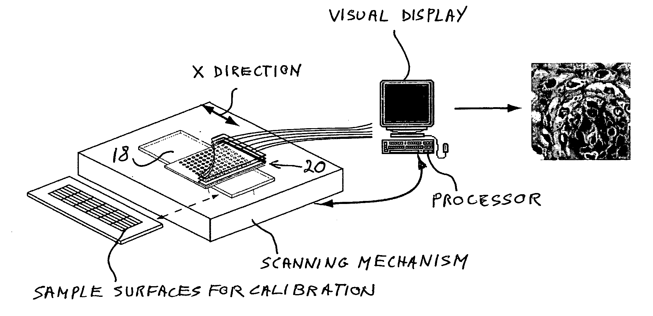
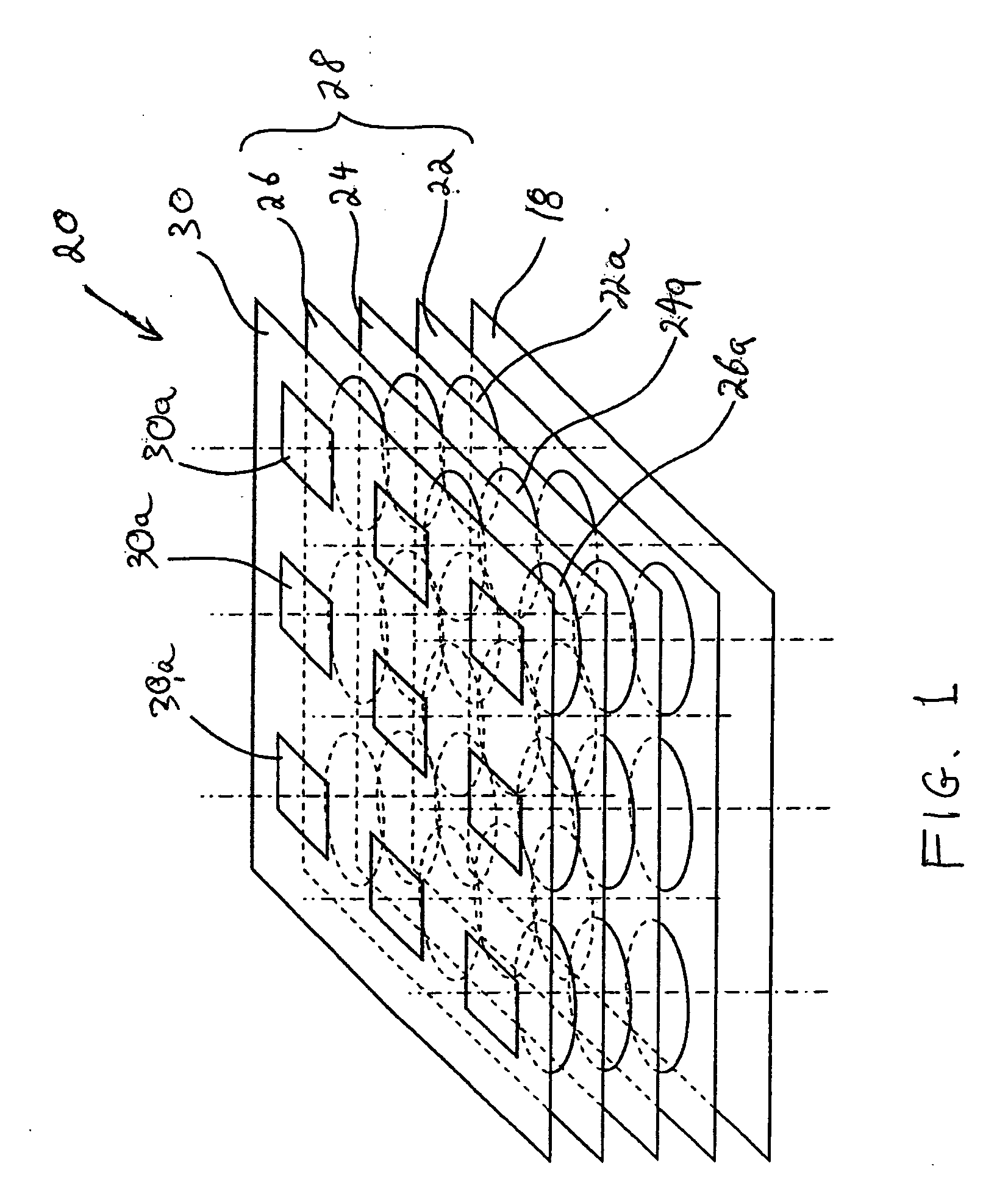
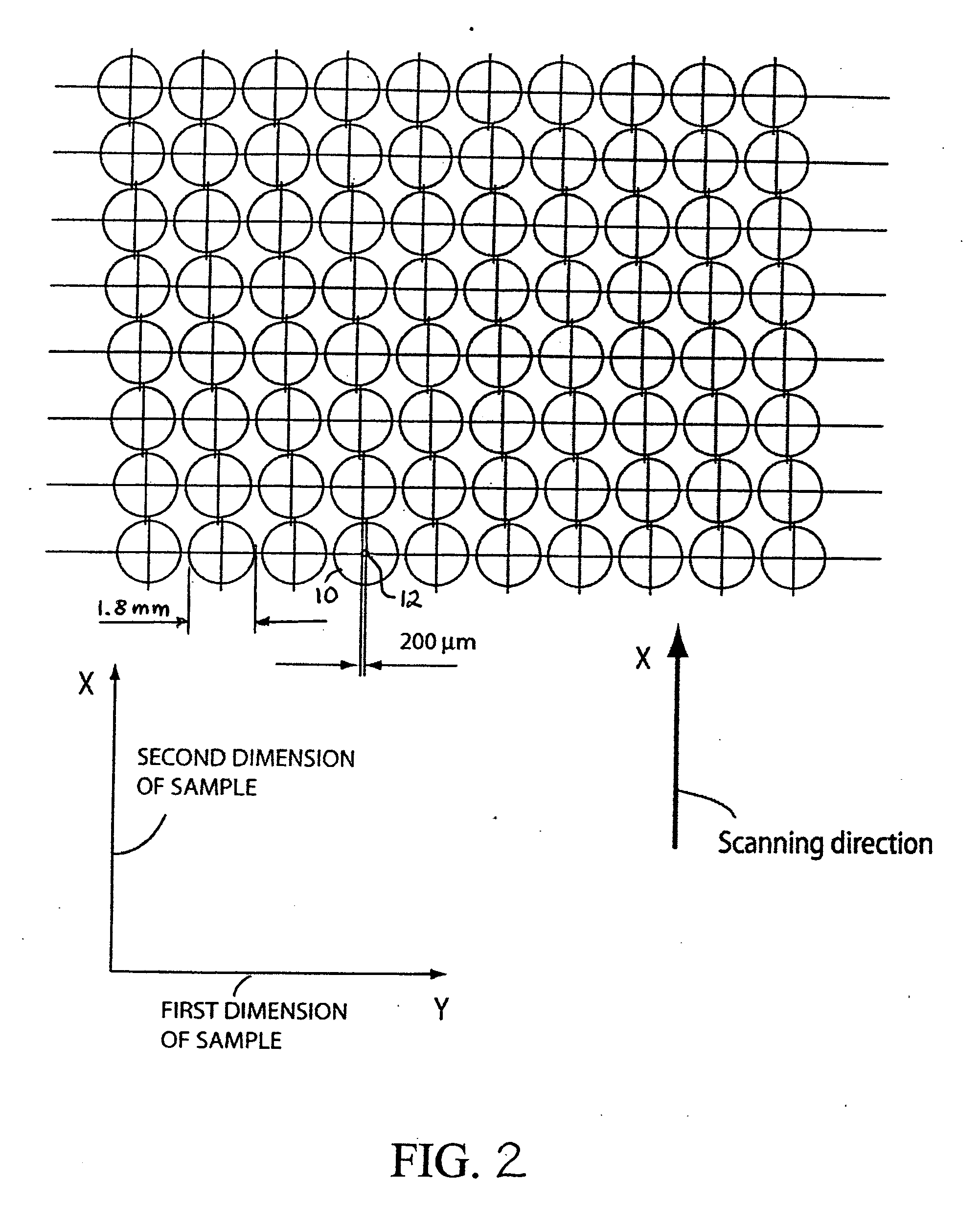
[0036] The invention was motivated by the realization that the images produced by data acquisition using an array microscope cannot be combined directly to produce a uniform composite image because of the unavoidable data incompatibilities produced by discrepancies in the optical properties of the various miniaturized microscopes in the array. The heart of the invention lies in the idea of normalizing such optical properties to a common basis, so that functionally the array of microscopes performs, can be viewed, and can be treated as a single optical device of uniform characteristics. As a result, each set of multiple images produced simultaneously at each scanning step can be viewed and treated as a single image that can be aligned and combined in conventional manner with other sets in a single operation to produce the composite image of a large area. The advantages of the invention are particularly useful when the array microscope is utilized with linear scanning and image swaths...
PUM
Abstract
An imaging apparatus consists of multiple miniaturized microscopes arranged into an array capable of simultaneously imaging respective portions of an object. A continuous linear translation approach is followed to scan the object and generate multiple image swaths of the object. In order to improve the quality of the composite image produced by concatenation of the image swaths, the performance of each microscope is normalized to the same base reference for each relevant optical-system property. Correction factors are developed through calibration to equalize the spectral response measured at each detector, to similarly balance the gains and offsets of the detector/light-source combinations associated with the various objectives, to correct for geometric misalignments between microscopes, and to correct optical and chromatic aberrations in each objective.
Description
RELATED APPLICATIONS [0001] This application is a continuation-in-part of U.S. Ser. No. 11 / 711,283, filed Feb. 27, 2007, which is a continuation-in-part of U.S. Ser. No. 10 / 637,486, filed Aug. 11, 2003, now U.S. Pat. No. 7,184,610, which is based on PCT / US02 / 08286, filed Mar. 19, 2002, and claims the benefit of priority of U.S. Provisional Application No. 60 / 276,498, filed Mar. 19, 2001, under 35 U.S.C. Section 119. This application is also a continuation-in-part of U.S. Ser. No. 10,687,432, filed Oct. 16, 2003.BACKGROUND OF THE INVENTION [0002] 1. Field of the Invention [0003] This invention is related in general to the field of microscopy. In particular, it relates to a novel approach for acquiring multiple image swaths of a large sample area using an array microscope and subsequently combining the swaths to form a good-quality high-resolution composite image. [0004] 2. Description of the Related Art [0005] Typical microscope objectives suffer from the inherent limitation of only ...
Claims
Application Information
Patent Timeline
Application Date:The date an application was filed.
Publication Date:The date a patent or application was officially published.
First Publication Date:The earliest publication date of a patent with the same application number.
Issue Date:Publication date of the patent grant document.
PCT Entry Date:The Entry date of PCT National Phase.
Estimated Expiry Date:The statutory expiry date of a patent right according to the Patent Law, and it is the longest term of protection that the patent right can achieve without the termination of the patent right due to other reasons(Term extension factor has been taken into account ).
Invalid Date:Actual expiry date is based on effective date or publication date of legal transaction data of invalid patent.