Biometric identification apparatus

Inactive Publication Date: 2008-02-14
HITACHI MEDIA ELECTORONICS CO LTD
View PDF2 Cites 48 Cited by
  • Summary
  • Abstract
  • Description
  • Claims
  • Application Information

AI Technical Summary

Benefits of technology

[0014]According to the present invention, liveness detection on an object to be identified can be accurately and rapidly performed with a simpler structure than that of conventional technology, by obtaining the optical transmittance of an object to be identified and comparing the transmittance with a previously-set transmittance threshold.
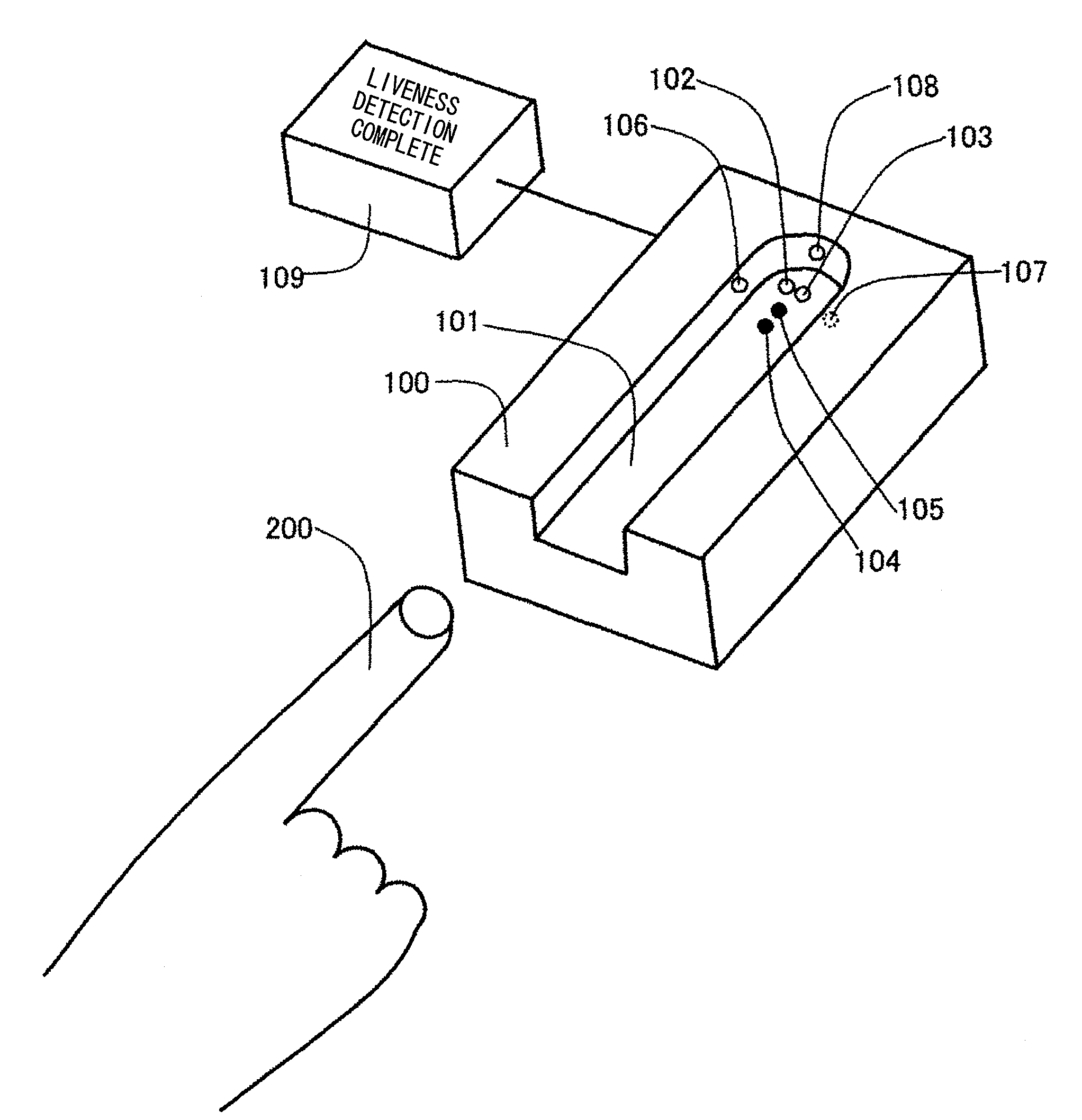
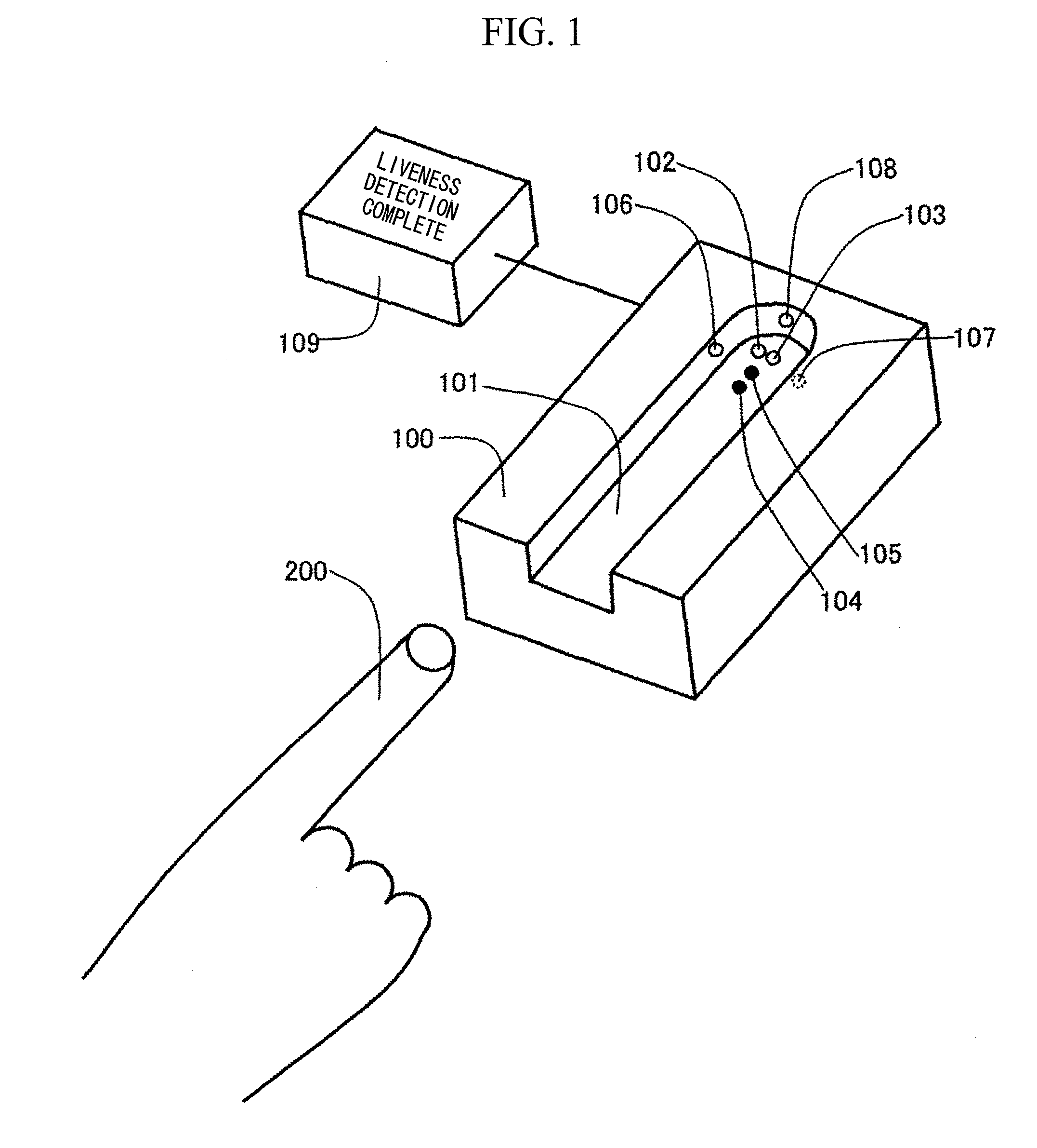
[0015]FIG. 1 is an external view of a biometric identification apparatus 100 according to an embodiment of the present invention. Light sources 102 and 103, such as LEDs or lasers, are disposed on the bottom surface of a finger placement portion 101 on which a finger 200 for biometric identification is placed. The light sources 102 and 103 are disposed so that the optical axes thereof form lines perpendicular to the bottom surface of the finger placement portion 101. Receiving surfaces of receivers 104 and 105 such as photodiode devices are disposed parallel to the bottom surface of the finger placement portion 101. On side surfaces that are perpendicular to the bottom surface of the finger placement portion 101, there are disposed light sources 106, 107, and 108 such as LEDs or lasers, so that the optical axes thereof form lines perpendicular to the side surfaces of the finger placement portion 101. The optical axes of the light sources 102 and 103 are perpendicular to the optical axes of the light sources 106, 107, and 108. The receiving surfaces of the receivers 104 and 105 are parallel to the optical axes of the light sources 106, 107, and 108. Reference numeral 109 denotes a display unit for displaying results of detection. In FIG. 1, the biometric identification apparatus 100 is separate from the display unit 109. The display unit 109, however, may be formed integrally with the biometric identification apparatus 100. The principle of the biometric identification apparatus 100 will be described below.
[0016]FIG. 2 shows spectra of the human fingers (test subjects A and B) and spectra of an eraser, soap, a screw driver grip (transparent plastic) and acetal resin as materials for spoof fingers. These spectra are measured with the light sources 102 and 103 and the receivers 104 and 105 disposed on the bottom surface of the finger placement portion 101 shown in FIG. 1. In FIG. 2, the horizontal axis indicates wavelengths, and the vertical axis indicates transmittance; that is, the light intensity ratio of the light emitted to the light detected. By selecting a wavelength at which the difference between transmittance of the light passing through the test subjects and transmittance of the light passing through materials for spoof fingers is large, it becomes possible to discriminate a living body from a fake living body. Thus, in FIG. 2, we focused on wavelengths λ1

Problems solved by technology

There is apprehension, however, that a possible fraudulent impostor who steals the registered information to create a sophisticated imitation of a l

Method used


Image

  • Biometric identification apparatus
  • Biometric identification apparatus
  • Biometric identification apparatus

Examples


Example

Embodiment 2

[0021]FIG. 6 shows an embodiment in which the biometric identification apparatus of the present invention is incorporated into biometric identification by fingerprint imaging. A fingerprint imaging unit 130 is incorporated into the bottom surface of a finger placement portion 101 of a biometric identification apparatus 120, so that the fingerprint imaging unit 130 does not interfere with the light sources 102, 103, 106, 107, and 108, and the receivers 104 and 105. Identification is made by first placing a finger in the finger placement portion 101, and then by performing determination of liveness detection. Thereafter, by drawing the finger back while lightly pressing the finger against the bottom surface of the finger placement portion 101, an image of the fingerprint can be obtained with the finger print imaging unit 130. In FIG. 6, while the biometric identification apparatus 120 and a display unit 109 are separate from each other, the display unit 109 may be integral...

Example

Embodiment 3

[0022]FIG. 7 shows an embodiment in which the biometric identification apparatus of the present invention is incorporated into biometric identification by vein imaging. A vein imaging unit 150 is incorporated into the bottom surface of a finger placement portion 101 of a biometric identification apparatus 140, so that the vein imaging unit 150 does not interfere with the light sources 102, 103, 106, 107, and 108, and the receivers 104 and 105. Moreover, as light sources for imaging veins, imaging light sources 110 are incorporated into a surface perpendicular to the surface where the vein imaging unit 150 is located. Identification is made by first placing a finger in the finger placement portion 101, and then by performing determination of liveness detection. Thereafter, the imaging light sources 110 are caused to emit light in a state where the finger remains placed on the finger placement portion 101. Thus, an image of the veins of the finger is obtained with the vein...

Example

Embodiment 4

[0023]In biometric identification, there are cases of failing to verify an authorized individual (false rejection) or of incorrectly verifying an unauthorized individual (false acceptance). In order to increase the accuracy of authentication, it is important that a photographed image; that is, biometric information, be stably obtained with uniform quality, and it is necessary that the finger be placed in a predetermined posture. Thus, a method for detecting a finger posture will be described below, the method using the light sources 106, 107, and 108 disposed on the side surfaces of the finger placement portion 101, and the receiver 104 or 105 disposed on the bottom surface of the finger placement portion 101 shown in FIG. 1.

[0024]FIG. 8 is a plan view showing a state in which a finger 200 is placed in a finger placement portion 101 as viewed from above, and showing a state in which a finger 200 is placed to the left side. In this state, the transmittance of the light em...


PUM


Abstract

[Problem] A biometric identification apparatus that can accurately and rapidly perform liveness detection with a simple structure.
[Solution] The apparatus includes a plurality of light sources 102, 103, 106, and 107, each having a wavelength different from one another, for emitting light to a finger 200 as an object to be identified, and receivers 104 and 105 for detecting the light passing through the finger. The ratio of the light emitted from the light sources to the light detected with the receivers is obtained as transmittance. Determination in liveness detection is made by comparing the transmittance with a previously-set threshold of transmittance.

Description

FIELD OF THE INVENTION[0001]The present invention relates to a biometric identification apparatus.DESCRIPTION OF THE RELATED ART[0002]A biometric identification technology based on biometric characteristics (fingerprints, veins, irises, etc.) of an individual has been proposed in many forms as means for identity verification. For example, the technology is used in automated teller machines (ATMs) of banks, and is used for access control to a controlled area. In addition, the technology is used when a person logs on a computer.[0003]Basically, the identity verification using a biometric identification apparatus is done by registering, in advance, biometric information of an individual to be identified, followed by a matching process with the stored information. There is apprehension, however, that a possible fraudulent impostor who steals the registered information to create a sophisticated imitation of a living body (a spoof of finger, iris, or the like) using the stolen information...

Claims


Application Information

Patent Timeline
IPC IPC(8): G01B11/00G01J3/00
CPCA61B5/0059A61B5/1172G06K9/0012G06K2009/00932G06K9/00912G06K2009/0006G06K9/00906G06V40/1341G06V40/1394G06V40/67G06V40/45G06V40/14
Inventor YOKOYAMA, SHINGOABE, TADAYUKISUGO, HIROMISATO, SHOICHI
Owner HITACHI MEDIA ELECTORONICS CO LTD
Why Eureka
Try Eureka