Gas Turbine Airfoil With Leading Edge Cooling

Active Publication Date: 2008-04-24
GENERAL ELECTRIC TECH GMBH
View PDF7 Cites 20 Cited by
  • Summary
  • Abstract
  • Description
  • Claims
  • Application Information

AI Technical Summary

Benefits of technology

[0017] Another aspect of the present invention therefore includes that, in contrast to the state-of-the-art, where either the cooling holes are simply conically widening at their exit, or are selectively conically widening in a radial direction only, according to the invention specifically two (or more) directions are defined in which the opening of the cooling holes is widening. On the one hand, there is the widening in the radial direction which leads to the asymmetry along the radial direction as defined by the forward inclination axis. On the other hand, there is the lateral widening, usually

Problems solved by technology

For very hot gas temperature conditions, cooling the leading edge with an internal cooling passage is usually not sufficient, requiring additional rows of holes drilled into the leading edge to pick-up some heat directly through the holes and to provide a layer of coolant film on the external surface.
However the interaction of the coolant flow ejected from theses rows of holes and the main hot gas flow can be difficult to predict, especially in situations where the stagnation line position can be uncertain due to changes of incidence angles.
While too small a pressure difference can result in an ingestion of hot gas into the film cooling hole, too large a pressure differen

Method used


Image

  • Gas Turbine Airfoil With Leading Edge Cooling
  • Gas Turbine Airfoil With Leading Edge Cooling
  • Gas Turbine Airfoil With Leading Edge Cooling

Examples


Example

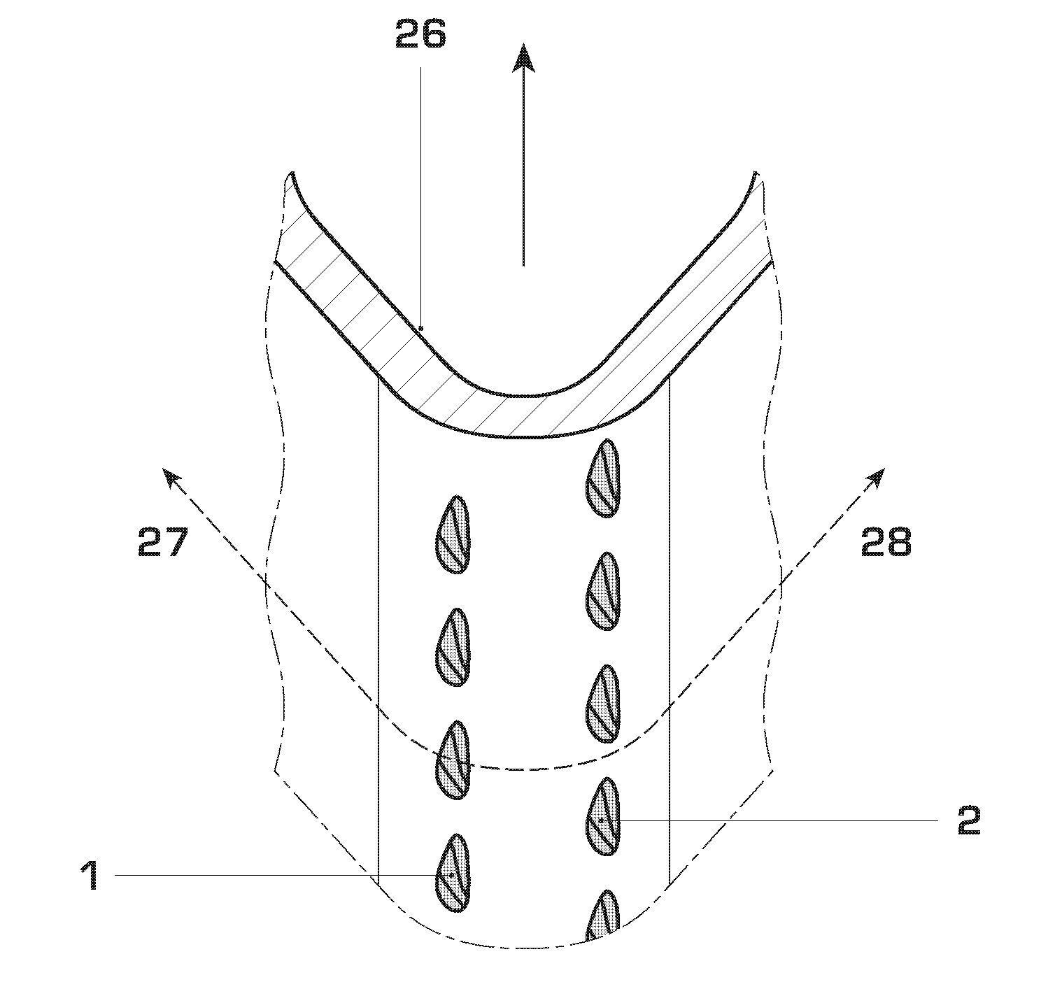
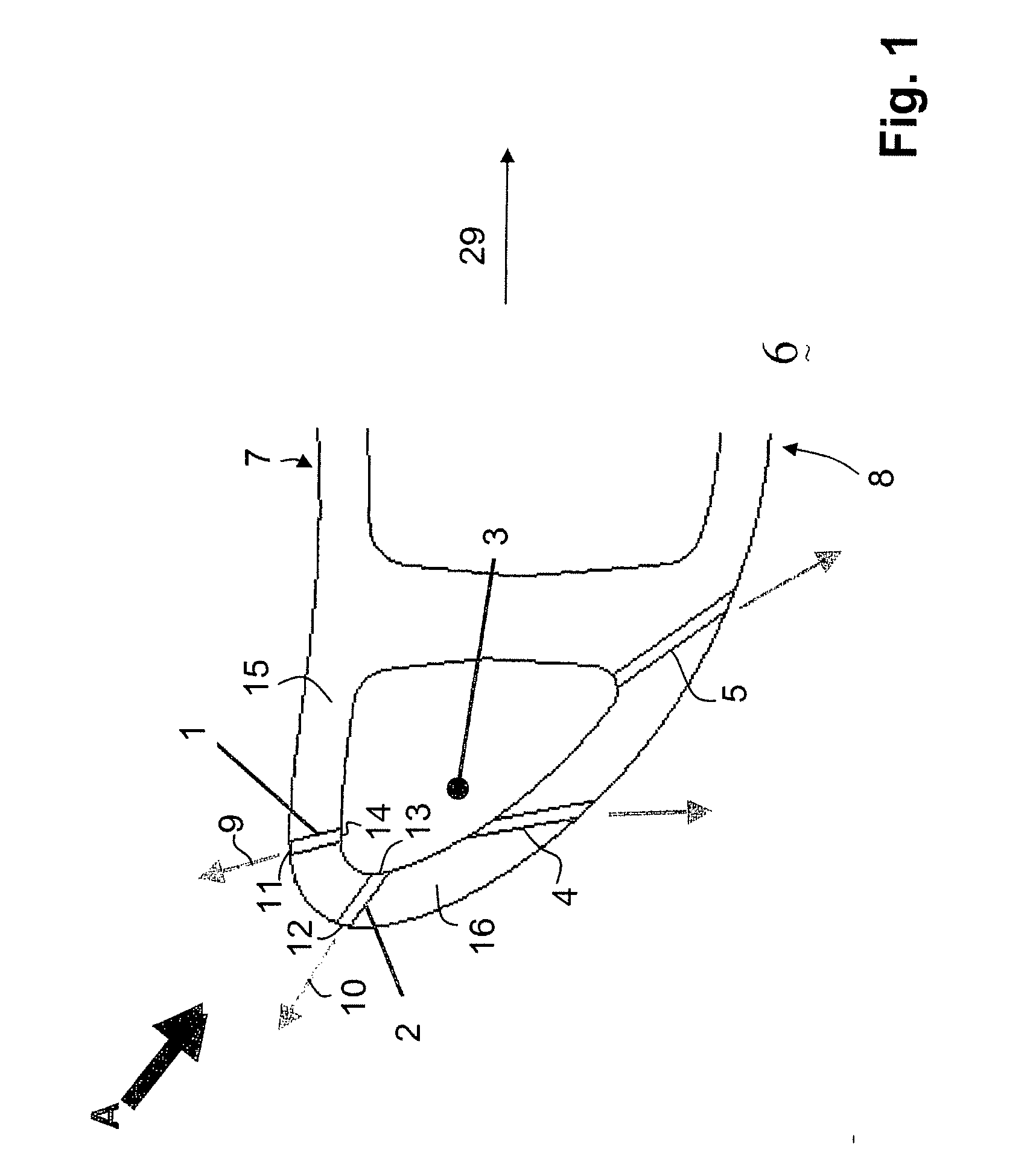
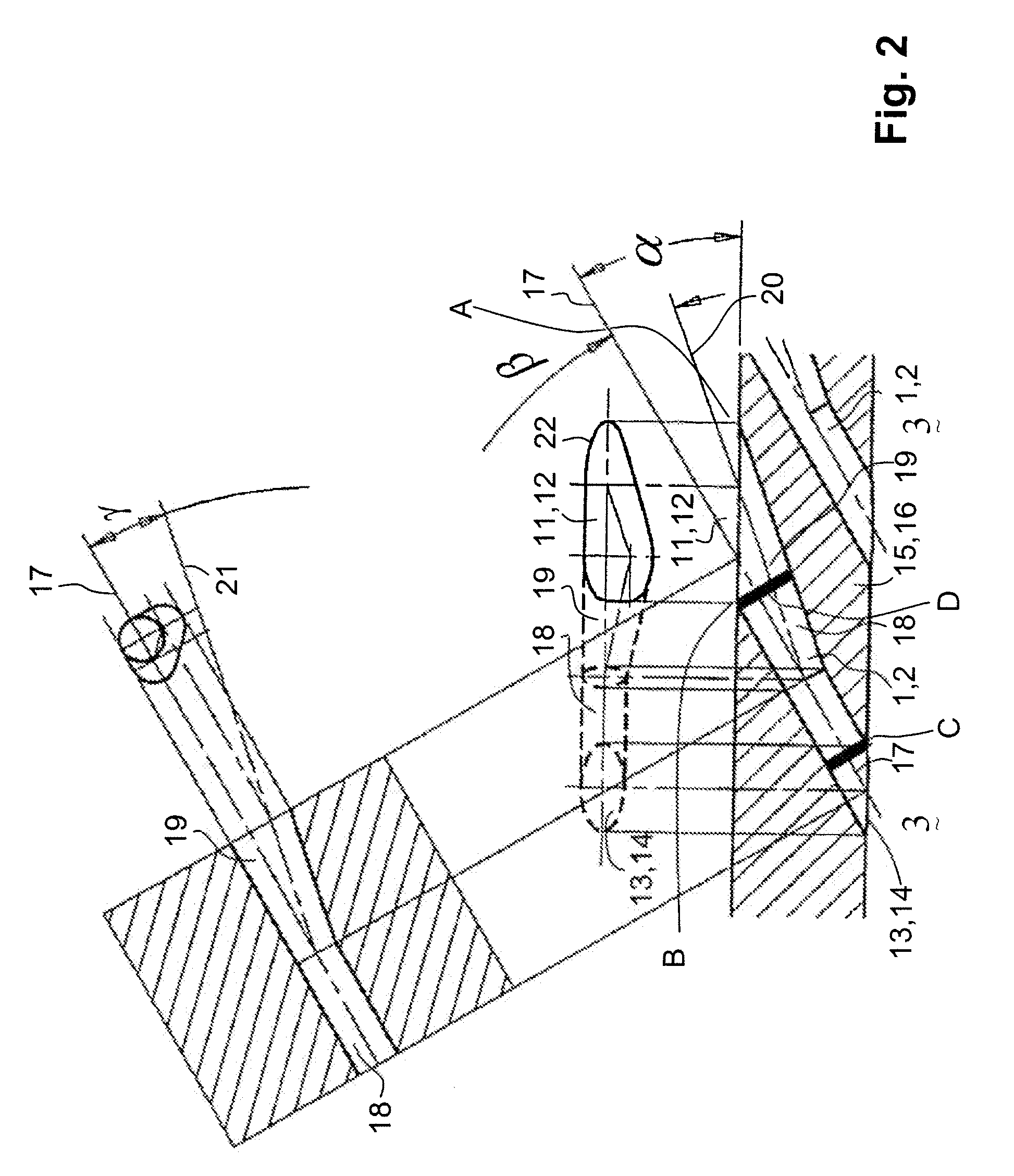
[0037] Referring to the drawings, which are for the purpose of illustrating the present preferred, exemplary embodiments of the invention and not for the purpose of limiting the same, FIG. 1 shows a cut essentially in a plane perpendicular to the radial direction of the row of gas turbine blades through the leading edge or shower head region of a gas turbine airfoil 6. The gas turbine airfoil 6 is given as a hollow body defined by a pressure side wall 15 and a suction sidewall 16, which at the leading edge converge in the shower head region or leading edge region, and which at the trailing edge 29 (not displayed) also converge.

[0038] Within the gas turbine airfoil 6 there is provided a plurality of cooling air passages, and in this specific embodiment there is provided one radial cooling air cooling air passage 3 in the leading edge region.

[0039] For cooling such an airfoil, on the one hand the internal circulation through the cooling air passages is effective, on the hand in addi...


PUM

PropertyMeasurementUnit
Angleaaaaaaaaaa
Angleaaaaaaaaaa
Angleaaaaaaaaaa

Abstract

A gas turbine airfoil (1) includes a pressure sidewall (15) and a suction sidewall (16), extending from a root to a tip and from a leading edge region to a trailing edge and having at least one cooling passage between the pressure sidewall (15) and the suction sidewall (16) for cooling air to pass through and cool the airfoil from within. One or several of the cooling passages (3) extend along the leading edge of the airfoil (1) and several film cooling holes (1,2) extend from the internal cooling passages (3) along the leading edge region to the outer surface of the leading edge region. The film cooling holes (1,2) each have a shape that is diffused in a radial outward direction of the leading edge of the airfoil (1) at least over a part of the length of the film cooling hole (1,2). Improved cooling in the leading edge region can be achieved because the cooling holes (1, 2) have a principal axis (17), and the shape is asymmetrically diffused in that it is diffused in the radial outward direction from the principal axis (17) along a forward inclination axis (20), and it is additionally diffused in a second lateral direction from the principal axis (17) along a lateral inclination axis (21).

Description

[0001] This application claims priority under 35 U.S.C. §119 to U.S. Provisional Application No. 60 / 823,511, of 25 Aug. 2006, the entirety of which is incorporated by reference herein.BACKGROUND OF THE INVENTION [0002] 1. Field of the Invention [0003] This invention pertains to a gas turbine airfoil and in particular to a cooling construction for its leading edge. [0004] 2. Brief Description of the Related Art [0005] Airfoils of gas turbines, turbine rotor blades, and stator vanes, require extensive cooling in order to keep the metal temperature below a certain allowable level and prevent damage due to overheating. Typically such airfoils are designed with hollow spaces and a plurality of passages and cavities for cooling fluid to flow through. The cooling fluid is typically air bled from the compressor having a higher pressure and lower temperature compared to the gas travelling through the turbine. The higher pressure forces the air through the cavities and passages as it transpor...

Claims


Application Information

Patent Timeline
IPC IPC(8): F01D5/08
CPCF01D5/186F05D2240/121Y10T29/49341F05D2250/314F05D2240/303
Inventor NAIK, SHAILENDRAVOGEL, GREGORY
Owner GENERAL ELECTRIC TECH GMBH
Why Eureka
Try Eureka