Apparatus and method for body tissue fixation

a body tissue and applicator technology, applied in the field of applicator and method for body tissue fixation, can solve the problems of increasing the complexity of surgical procedures, affecting the effect of the surgical procedure, so as to prevent the displacement of the fixation devi

Inactive Publication Date: 2008-04-24
MERLOT ORTHOPEDIX +1
View PDF22 Cites 68 Cited by
  • Summary
  • Abstract
  • Description
  • Claims
  • Application Information

AI Technical Summary

Benefits of technology

[0007]In an embodiment of the present invention, a body tissue fixation apparatus is described. The body tissue fixation apparatus includes a plate having oppositely disposed outer and tissue-contacting surfaces, and at least one fixation hole extending between the outer and tissue-contacting surfaces along a longitudinal axis. The fixation hole is defined in part by an inner hole surface having at least one serration. The plate is adapted for affixation to at least one body tissue member. At least one fixation device of the body tissue fixation apparatus has a shank and a head portion, the shank being insertable through the fixation hole in the plate to affix the plate to the body tissue member upon rotation of the head portion. At least one deformable member is connected to the head portion, the deformable member extending laterally in a direction substantially perpendicular to the longitudinal axis and being adapted to deflect to engage with at least one serration formed on the inner hole surface. Engagement between the deformable member and the serration helps to prevent displacement of the fixation device within the fixation hole.
[0008]In an embodiment of the present invention, a method for securing a plate to a body tissue of a patient is described. A plate having oppositely disposed outer and tissue-contacting surfaces and at least one fixation hole extending between the outer and tissue-contacting surfaces along a longitudinal axis is provided. The fixation hole is defined in part by an inner hole surface having at least one serration. The plate is placed into a desired orientation with the body tissue. At least one fixation device having a shank with spaced-apart first and second shank ends separated along the longitudinal axis is provided. The fixation device has a head portion having top and bottom surfaces spaced apart by a main body. The first shank end extends from the bottom surface. The head portion includes at least one void extending longitudinally through the head portion body between the top and bottom head portion faces to define at least one deformable member extending from the main body. The second shank end is inserted into the fixation hole and into engagement with the body tissue. The head portion is rotated to cause the shank to sink into the body tissue and the head portion to engage the plate. The deformable member is deflected away from an initial position. A serration is engaged with the deformable member to help prevent the fixation device from displacement within the fixation hole.

Problems solved by technology

Unfortunately, many of the known bone screws can be susceptible to toggling within the body tissue and can also pull out of the body tissue longitudinally due to the substantial forces on the screws from human body movement and muscle memory.
However, use of such a nut increases the complexity of the surgical procedure and may not be possible in a desired application if access to the opposing side of the bone is limited.
Additionally, known bone screws have a tendency to work free from the bone by rotating in a direction opposite the insertion rotation direction, thereby “backing out” of engagement with the bone and any corrective device through which the bone screw extends.
Though this backward rotation differs from pullout due to toggling, the end result is still an undesirable displacement of the bone screw from the bone and / or an associated corrective device, which may necessitate additional surgeries and cause renewed patient trauma.

Method used


Image

  • Apparatus and method for body tissue fixation
  • Apparatus and method for body tissue fixation
  • Apparatus and method for body tissue fixation

Examples


first embodiment

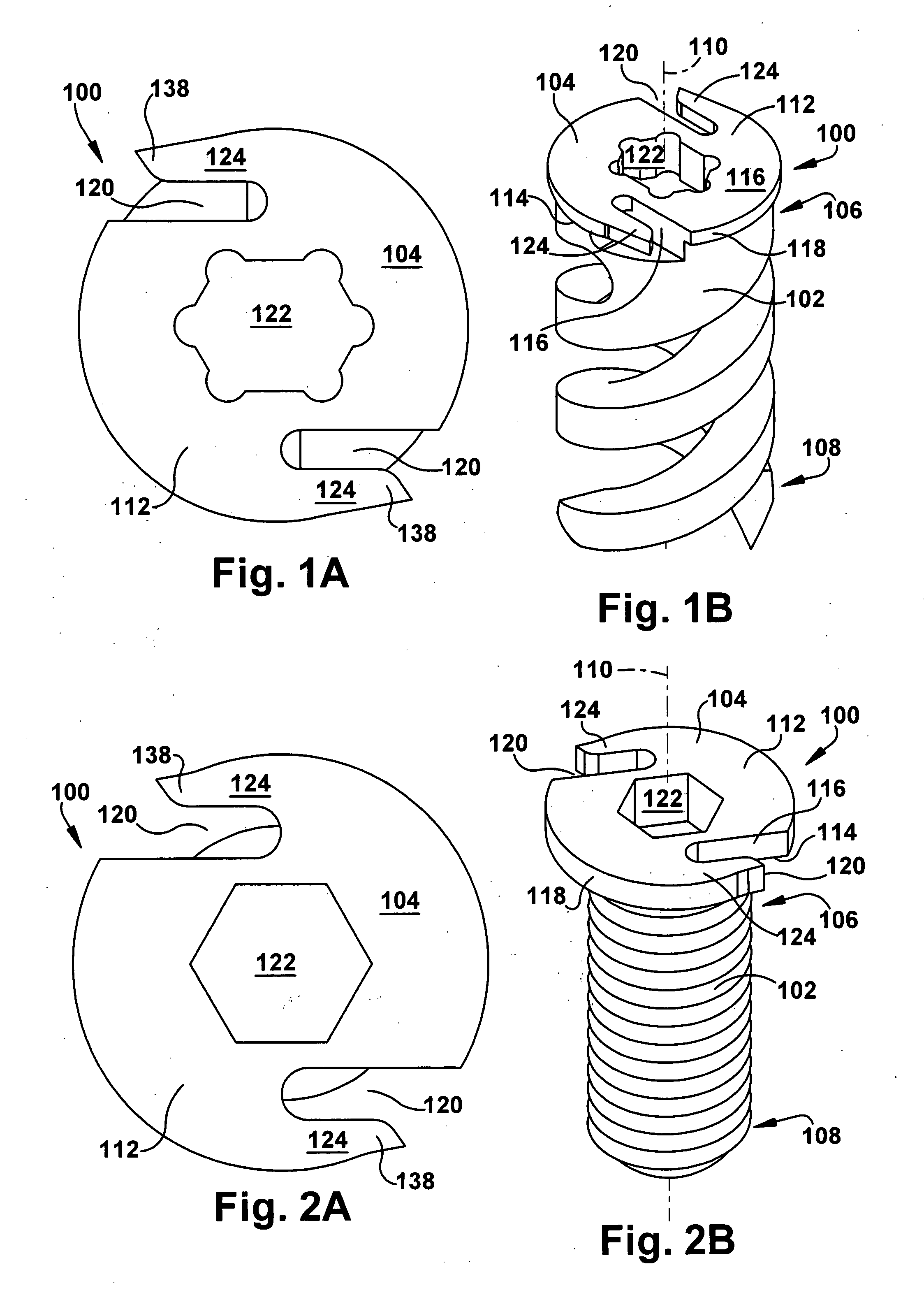
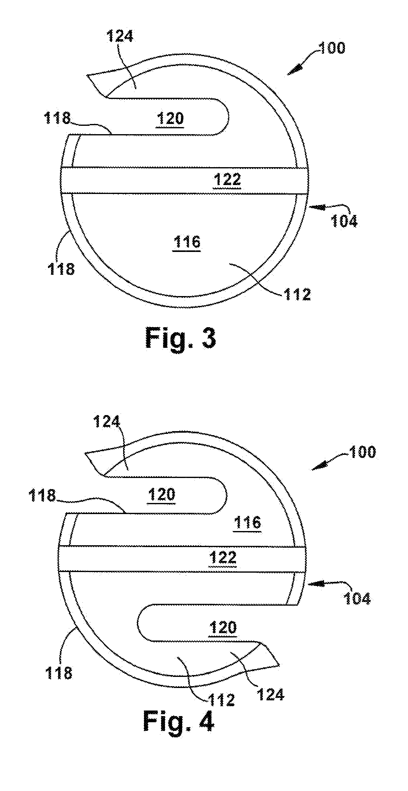
[0065]In accordance with the present invention. FIGS. 1A, 1B, 2A, 2B, 3, 4, 5A, 5B, and 5C depict a body tissue fixation apparatus according to the present invention. Though the present invention is described herein as being used with bone, the fixation apparatus of any embodiment of the present invention may be used with any suitable body tissue, such as, but not limited to, bone, tendons, fascia, cartilage, and dentin. The term “bone” is used throughout this description merely for clarity and ease of reference and does not restrict the potential use of the present invention in any desired application.

[0066]The fixation apparatus includes a fixation device 100 shown in FIGS. 1A, 1B, 2A, and 2B, which includes a shank 102 and a head portion 104. The shank 102 is adapted for engagement with a bone member (not shown) or other body tissue. The shank 102 has spaced-apart first and second shank ends 106 and 108, respectively, separated along a longitudinal axis 110. The longitudinal axis...

third embodiment

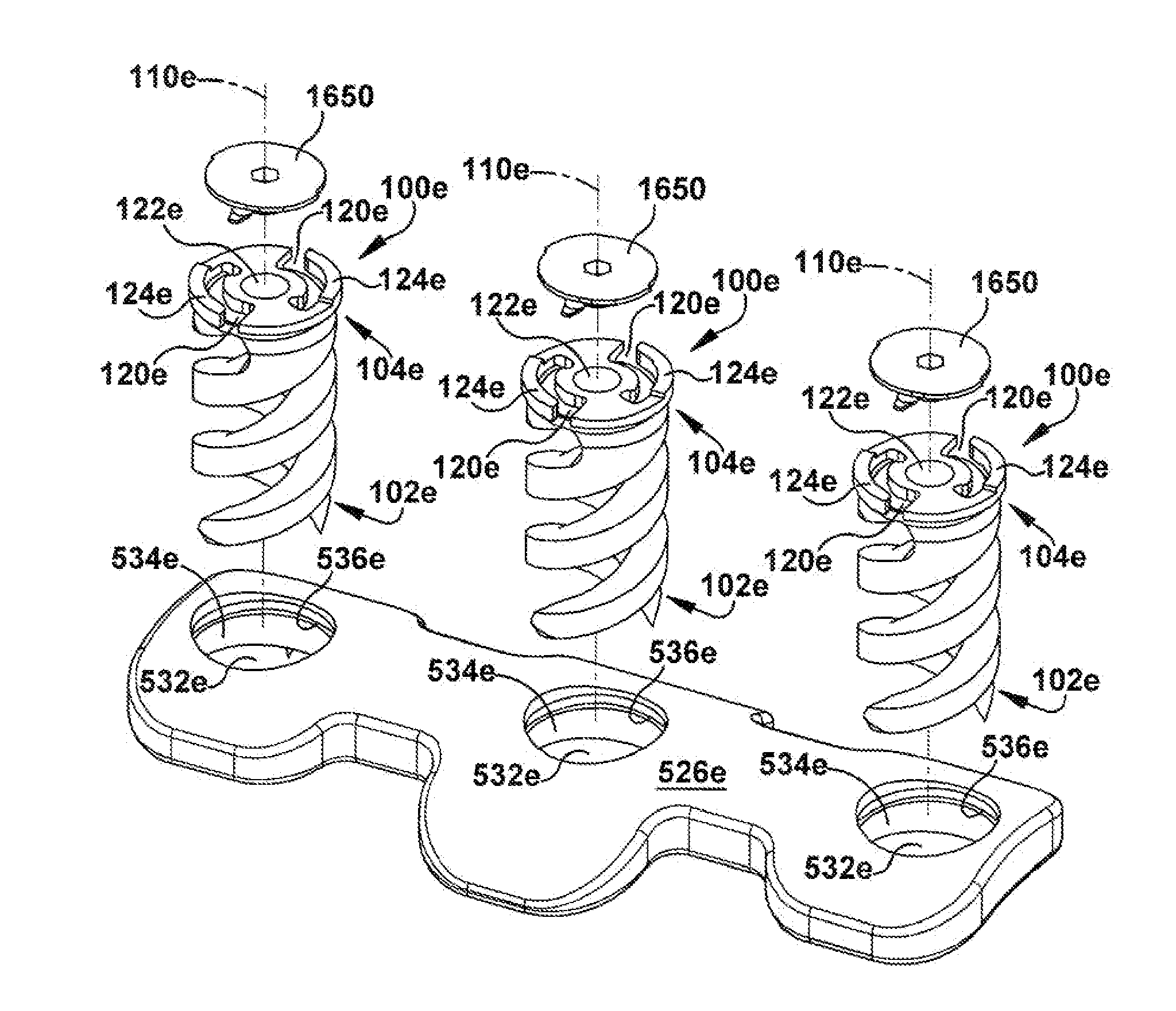
[0083]The fixation device 100c shown in FIGS. 8, 9A, and 9B includes a deformable member 124c having a tip 138c protruding longitudinally toward the shank 102c. The plate 528c, shown in FIGS. 10A, 10B, and 10C, includes at least one serration 536c extending laterally with respect to the longitudinal axis 110c, with a plurality of serrations circumferentially spaced about a periphery of the fixation hole 532c to form a shelf-like array around the inner hole surface 534c, as depicted. As the fixation device 100c is inserted through the fixation hole 532c in the plate 528c, the deformable member 124c of the third embodiment deflects longitudinally in a ratcheting manner to engage at least one serration 536c.

sixth embodiment

[0084]The engagement between the deformable member 124c and at least one serration 536c will resist displacement of the fixation device 100c by backing out due to rotation in a direction opposite the insertion direction. Should a longitudinal displacement force be exerted upon the fixation device 100c, however, the deformable member 124c may be shifted longitudinally and lose engagement with the serration 536c. Therefore, a holddown feature, similar to those discussed with respect to the sixth embodiment below, may be provided to exert a longitudinal pressure upon at least a portion of the deformable member 124c and thereby maintain engagement between the deformable member and at least one serration 536c. This holddown feature can be readily designed by one of ordinary skill in the art. Suitable holddown features may include, for example, a tooth formed integrally with the fixation device 100c or a separate snap ring or cover plate, any of which could be adapted to engage with a str...


PUM


Abstract

A body tissue fixation apparatus includes a plate having oppositely disposed outer and tissue-contacting surfaces, and at least one fixation hole extending between the outer and tissue-contacting surfaces along a longitudinal axis. The fixation hole is defined in part by an inner hole surface having at least one serration. The plate is adapted for affixation to at least one body tissue member. At least one fixation device of the body tissue fixation apparatus has a shank and a head portion, the shank being insertable through the fixation hole in the plate to affix the plate to the body tissue member upon rotation of the head portion. At least one deformable member is connected to the head portion, the deformable member extending laterally in a direction substantially perpendicular to the longitudinal axis and being adapted to deflect to engage with at least one serration formed on the inner hole surface. Engagement between the deformable member and the serration helps to prevent displacement of the fixation device within the fixation hole. A method for using the body tissue fixation apparatus is also described.

Description

TECHNICAL FIELD[0001]The present invention relates to an apparatus and method for affixing body tissue.[0002]This application claims priority from U.S. Provisional Application No. 60 / 832,417, filed Jul. 23, 2006, the subject matter which is incorporated herein by reference.BACKGROUND OF THE INVENTION[0003]Bone screws are used in the medical field for a variety of purposes. Typical uses for bone screws, which may be also referred to as bone anchors and will be discussed as such below, include treating a bone fracture, attaching a corrective device to parts of a fractured bone in an area adjacent to the fracture, and attaching a corrective device to a group of bones. For example, bone screws could be used to attach a plate to one or more vertebrae of a spinal column, such as in one or more of the anterior cervical, anterior or lateral thoracic, anterior or lateral lumbar, anterior lumbosacral or anterior sacral positions.[0004]Bone screws may be used to mount suitable instrumentation—...

Claims


Application Information

Patent Timeline
Patent Type & Authority Applications(United States)
IPC IPC(8): A61B17/80A61B17/86
CPCA61B17/8052A61B17/869A61B17/8605
Inventor ERICKSON, PAUL LAWRENCELISY, JASON A.HARRINGTON, STEPHANIE ADI SOULENLIEBERMAN, ISADOR H.KEVERLINE, STEPHEN EDWARD
Owner MERLOT ORTHOPEDIX
Why Eureka
Try Eureka