Extender Cuff for Branch Vessel

a branch vessel and extension cuff technology, applied in the field of intravascular devices and methods, to achieve the effect of avoiding associated costs

Inactive Publication Date: 2008-04-24
MEDTRONIC VASCULAR INC
View PDF15 Cites 28 Cited by
  • Summary
  • Abstract
  • Description
  • Claims
  • Application Information

AI Technical Summary

Benefits of technology

[0007]In accordance with one example, a modular graft assembly includes a main graft, a lower extender cuff and an upper extender cuff. By rotating and/or telescoping the main graft, the lower extender cuff, and the upper extender cuff relative to one another, variations in the radial and longitudinal positions of branch vesse

Problems solved by technology

Unfortunately, a vessel structure is by nature tortuous,

Method used


Image

  • Extender Cuff for Branch Vessel
  • Extender Cuff for Branch Vessel
  • Extender Cuff for Branch Vessel

Examples


Embodiment Construction

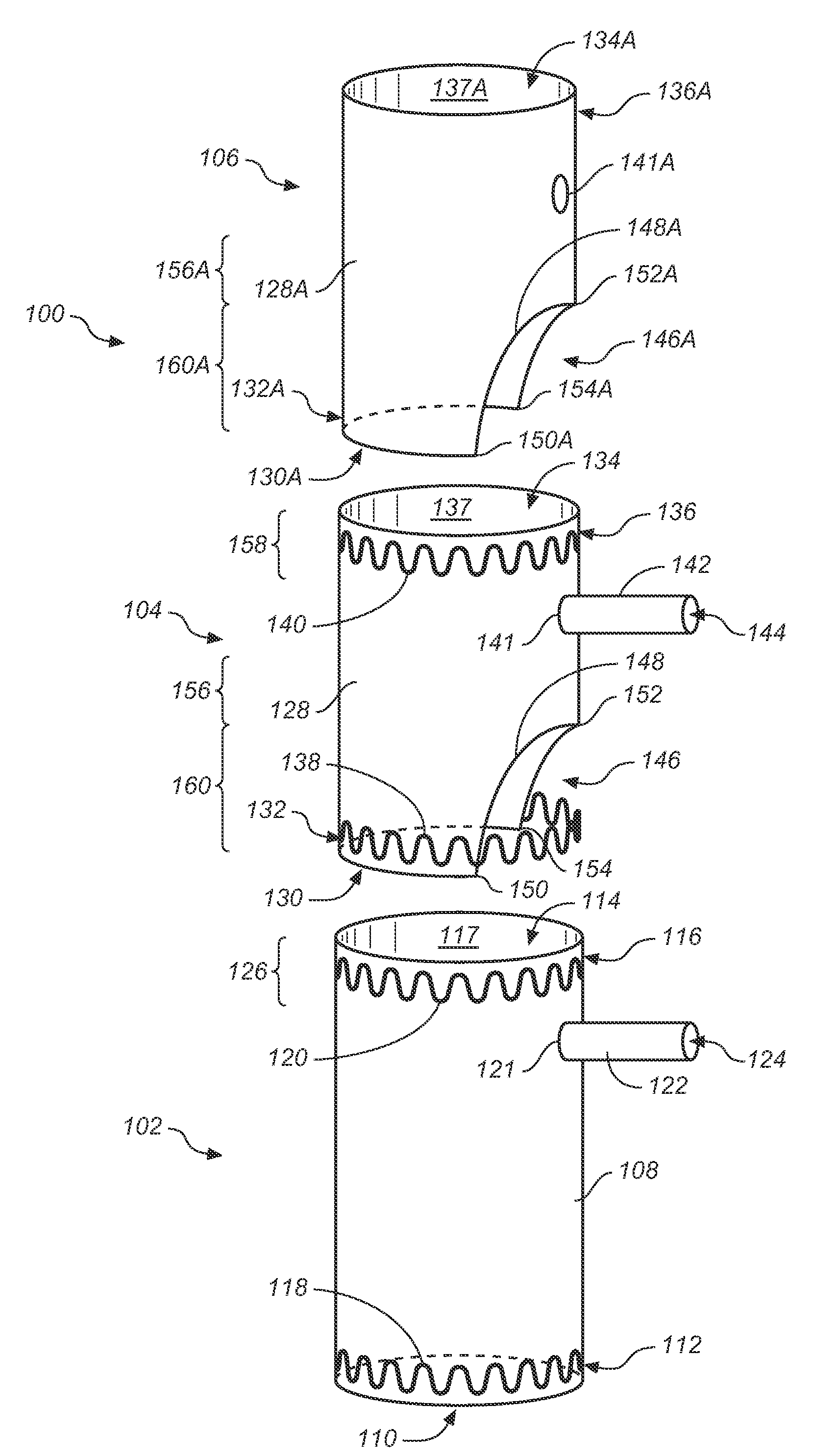
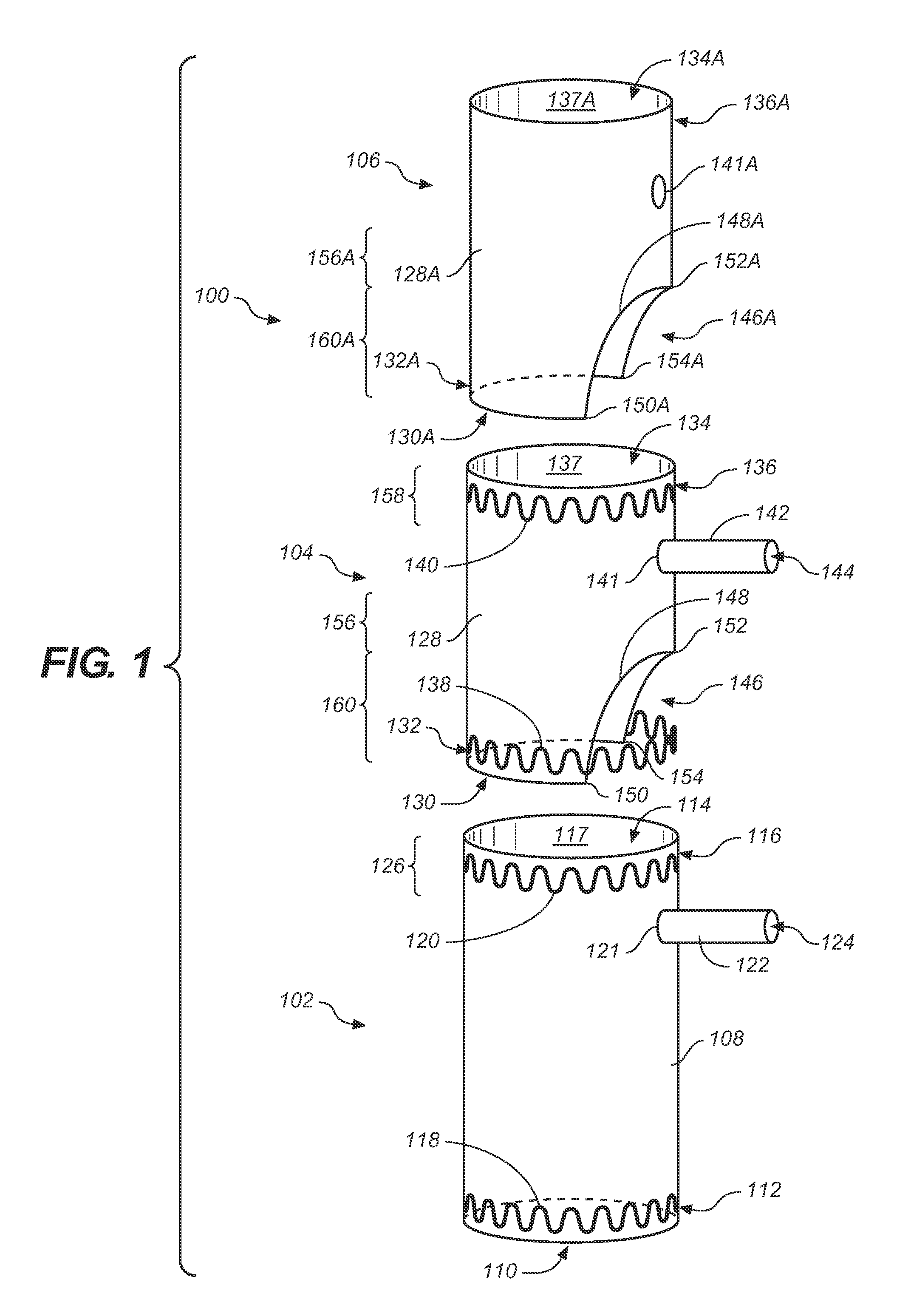
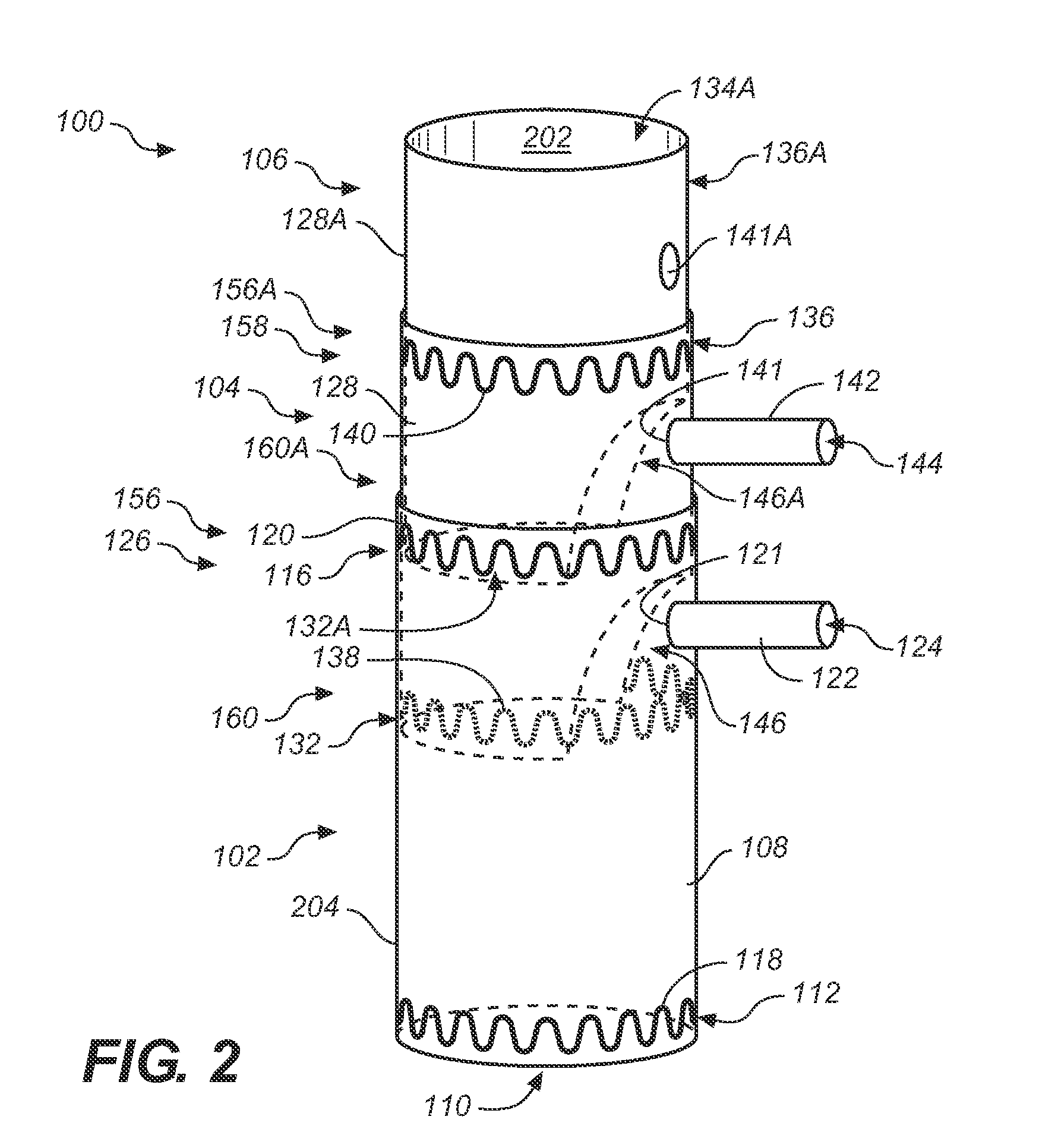
[0013]In accordance with one example, referring to FIG. 1, a modular graft assembly 100 includes a main graft 102, a lower extender cuff 104 and an upper extender cuff 106. Referring now to FIG. 3, by rotating and / or telescoping main graft 102, lower extender cuff 104, and upper extender cuff 106 relative to one another, variations in the radial and longitudinal positions of branch vessels 304, 306, 308 are readily accommodated by modular graft assembly 100. Accordingly, an aneurysm 304 is excluded while at the same time collateral flow to branch vessels 304, 306, 308 is provided. Further, custom fabrication of a graft assembly to accommodate the vessel structure of a particular patient and the associated costs are avoided.

[0014]More particularly, FIG. 1 is an exploded perspective view of a modular graft assembly 100 including a main graft 102, a lower, e.g., first, extender cuff 104, and an upper, e.g., second, extender cuff 106 in accordance with one embodiment.

[0015]Main graft 10...


PUM


Abstract

A modular graft assembly includes a main graft, a lower extender cuff and an upper extender cuff. By rotating and/or telescoping the main graft, the lower extender cuff, and the upper extender cuff relative to one another, variations in the radial and longitudinal positions of branch vessels are readily accommodated by the modular graft assembly. Accordingly, an aneurysm in a main vessel is excluded while at the same time collateral flow to branch vessels is provided. Further, custom fabrication of a graft assembly to accommodate the vessel structure of a particular patient and the associated costs are avoided.

Description

BACKGROUND OF THE INVENTION[0001]1. Field of the Invention[0002]The present invention relates to an intra-vascular device and method. More particularly, the present invention relates to a device for treatment of luminal, i.e., intra-vascular, diseases.[0003]2. Description of Related Art[0004]A conventional stent-graft typically included a radially expandable reinforcement structure, formed from a plurality of annular stent rings, and a cylindrically shaped graft material defining a lumen to which the stent rings were coupled. Stent-grafts are well known for use in tubular shaped human vascular or other body vessel.[0005]To illustrate, endovascular aneurysmal exclusion is a method of using a stent-graft to exclude pressurized fluid flow from the interior of an aneurysm, thereby reducing the risk of rupture of the aneurysm and the associated invasive surgical intervention. Although the aneurysm is excluded, it is important that the stent-graft does not occlude fluid flow to branch ves...

Claims


Application Information

Patent Timeline
IPC IPC(8): A61F2/06
CPCA61F2/07A61F2002/061A61F2220/0033A61F2250/0065A61F2/89A61F2002/075
Inventor ERICKSON, DAVIDGANESAN, PREMA
Owner MEDTRONIC VASCULAR INC
Why Eureka
Try Eureka