

Method for producing artificial fishing bank
A production method and fish reef technology, applied in the field of artificial fish reef production, can solve the problems of difficulty in obtaining materials and high manufacturing costs, and achieve the effects of simple process, easy access to raw materials, good fish collection effect and aesthetics
- Summary
- Abstract
- Description
- Claims
- Application Information
AI Technical Summary
Problems solved by technology
Method used
Image


Examples
example 1
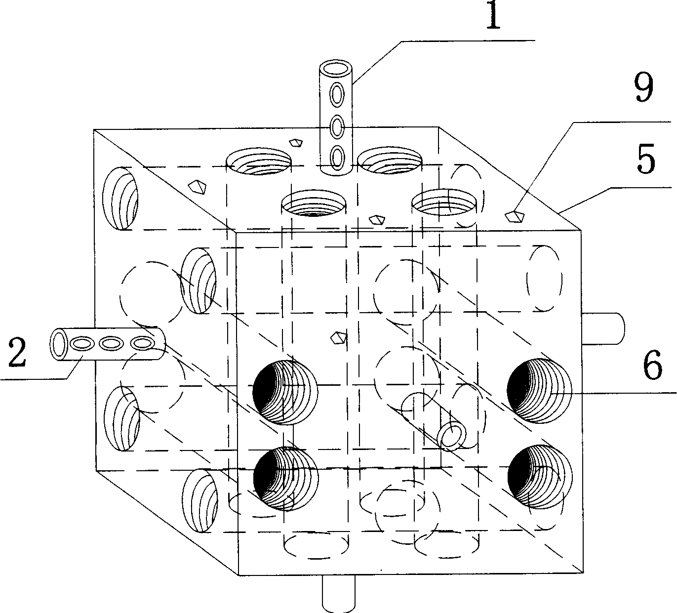
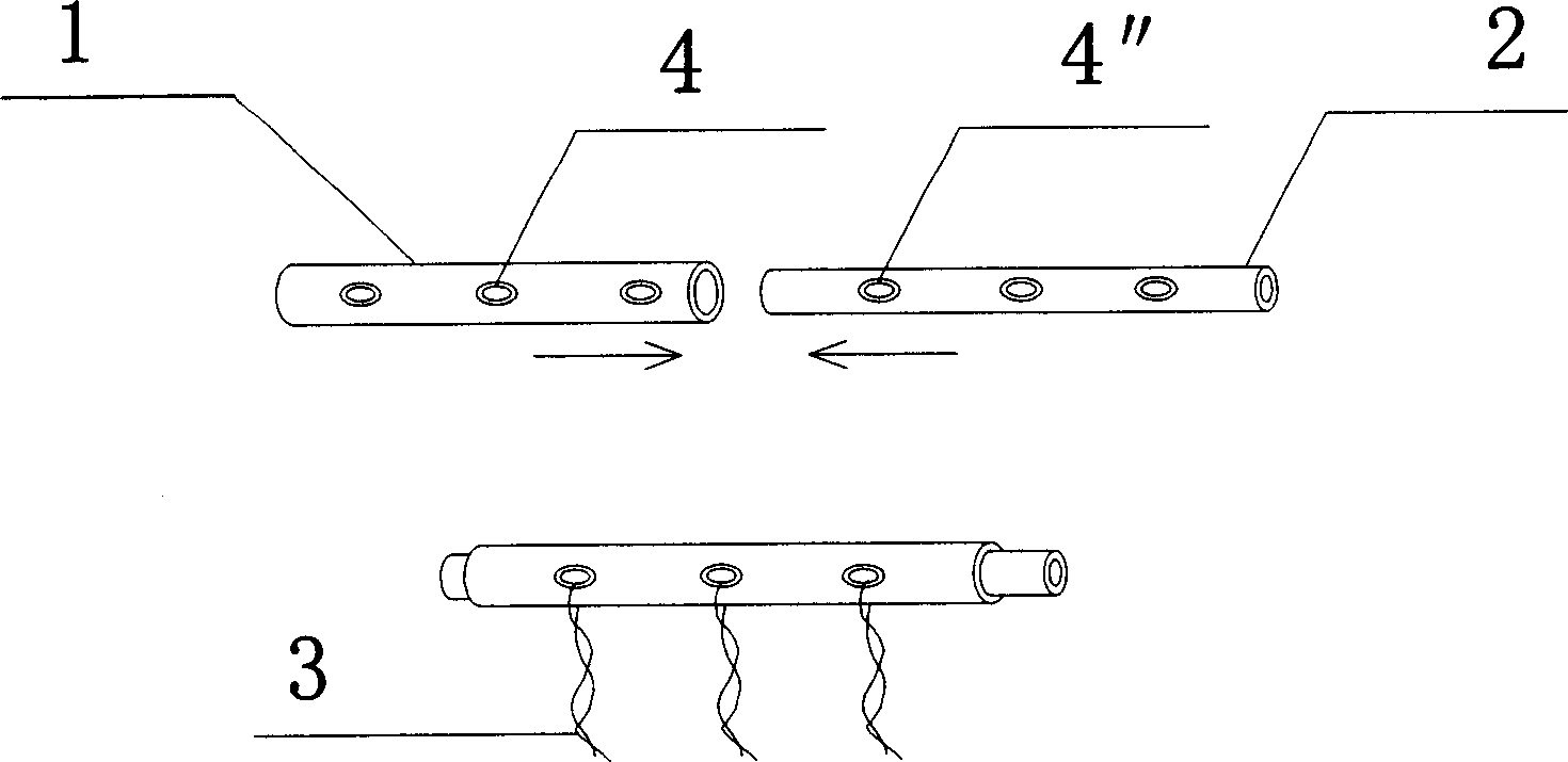
[0015] Example 1: First, a certain amount of steel bars are used to bind a cube-shaped skeleton 5 . The volume is 1 cubic meter. Fill fine sand inside the columnar polyethylene hose mold 6, and put it into the fish reef skeleton 1 horizontally. Then use cement, sand, and stone to mix into concrete at a mixing ratio of 3:2:3, and fill it into the fish reef skeleton with polyethylene hoses, and at the same time place it on the 6 sides of the cube. Connect member 1 or 2. When arranging the connecting member, at least one of the cube faces needs to place the connecting member 1 or 2. When the concrete is solidified, the fine sand in the polyethylene hose mold can be poured out, and the polyethylene hose mold can be pulled out from the reef at the same time. When the fish reef skeleton concrete is about to solidify, add a certain amount of stones 9 on its surface, allow the stones to be fixed on the fish reef surface to form a protrusion, or wash the fish reef surface with water...
example 2
[0016] Example 2: First, bind a certain amount of steel bars into a spherical skeleton 7 . The volume is 1 cubic meter. Be full of soil in conical polyethylene hose mold 8 inside, and it is inserted in the fish reef skeleton 7 towards the spherical center. Then use cement, sand and stone to mix into concrete at a mixing ratio of 5:4:4. And fill it into the fish reef skeleton that the polyethylene hose is placed on, and at the same time insert the connecting member 1 or 2 respectively on the spheroid. When placing the connecting member, at least one point on the spherical surface needs to install the connecting member 1 or 2. When the concrete is solidified, the soil in the polyethylene hose mold can be poured out, and the polyethylene hose mold can be pulled out from the reef at the same time. When the fish reef skeleton concrete is about to solidify, add a certain amount of self-stones 9 on its surface, let the stones be fixed on the fish reef surface to form a protrusion,...
PUM
 Abstract
Description
Claims
Application Information