Encoder, method of encoding, and computer-readable recording medium

a technology of computer-readable recording medium and encoder, which is applied in the field of encoder, method of encoder, and computer-readable recording medium, and can solve the problems of increasing quantization error in core encoder, degrading sound quality, and reducing the value of “y”

Active Publication Date: 2008-04-24
FUJITSU LTD
View PDF10 Cites 41 Cited by
  • Summary
  • Abstract
  • Description
  • Claims
  • Application Information

AI Technical Summary

Benefits of technology

[0017] It is an object of the present invention to at least

Problems solved by technology

That is, if a number of encoding bits is small, the quantization error increases so that the sound quality is degraded, and if the number of encoding bits is large, the quantization error decreases so that the sound quality is improved.
Accordingly, there is a problem in that if the value

Method used


Image

  • Encoder, method of encoding, and computer-readable recording medium
  • Encoder, method of encoding, and computer-readable recording medium
  • Encoder, method of encoding, and computer-readable recording medium

Examples


first embodiment

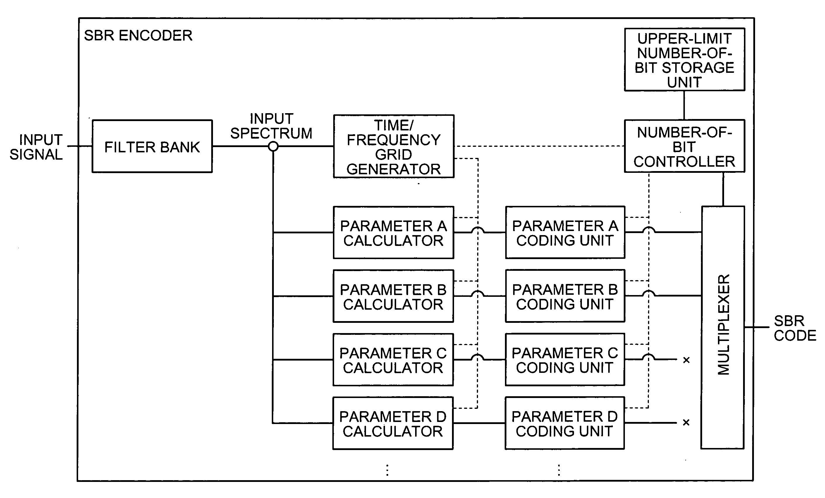
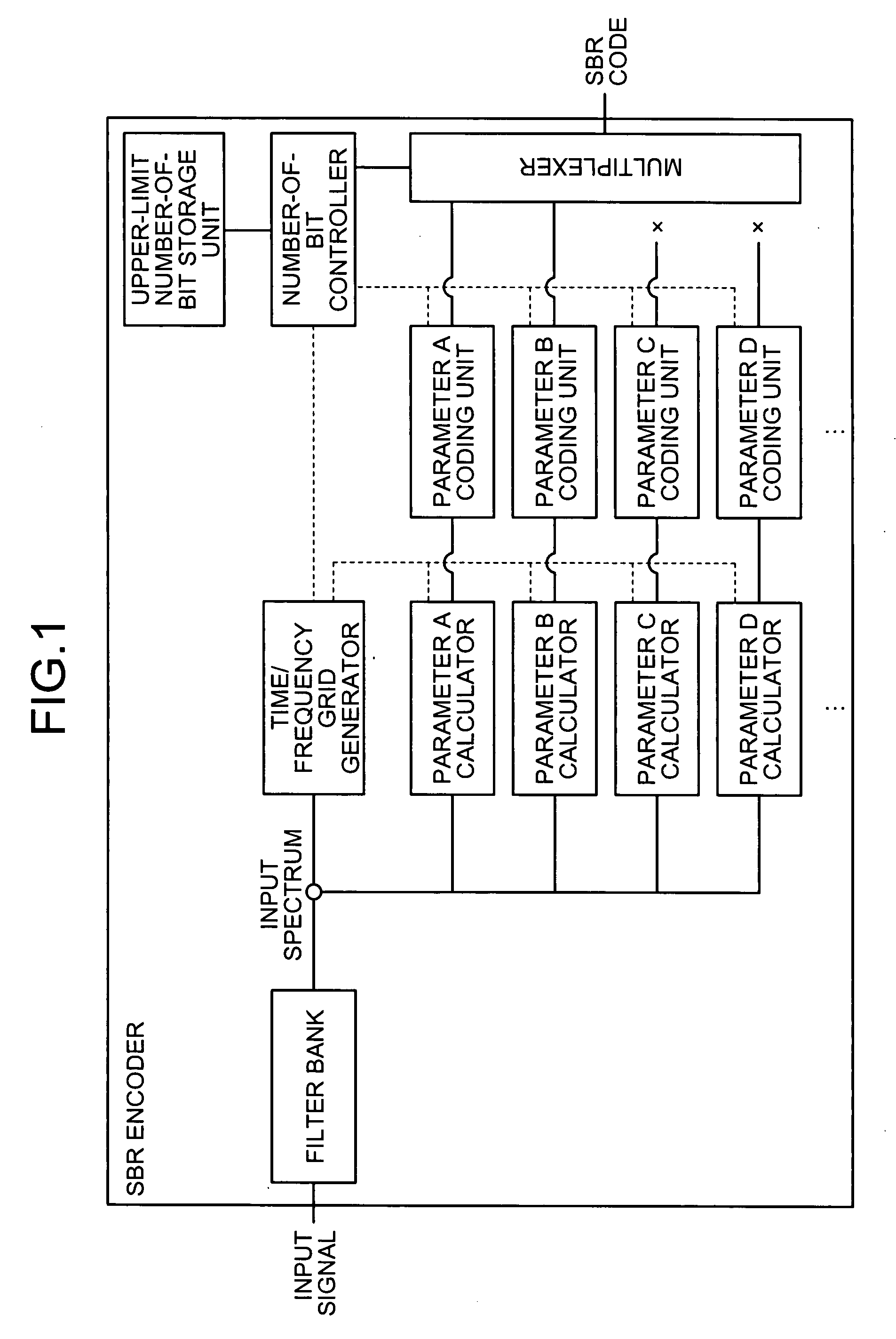
[0054] In this manner, according to the SBR encoder in the first embodiment, when it is assumed that the order of parameters affecting the sound quality the most is parameter A, parameter B, parameter C, and parameter D, the parameters are encoded in an order started from parameter A. Thereafter, when the upper limit of the number of bits is reached, the parameters are discarded. As a result, a local increase in the number of bits of the encoded data of high-frequency component can be avoided.

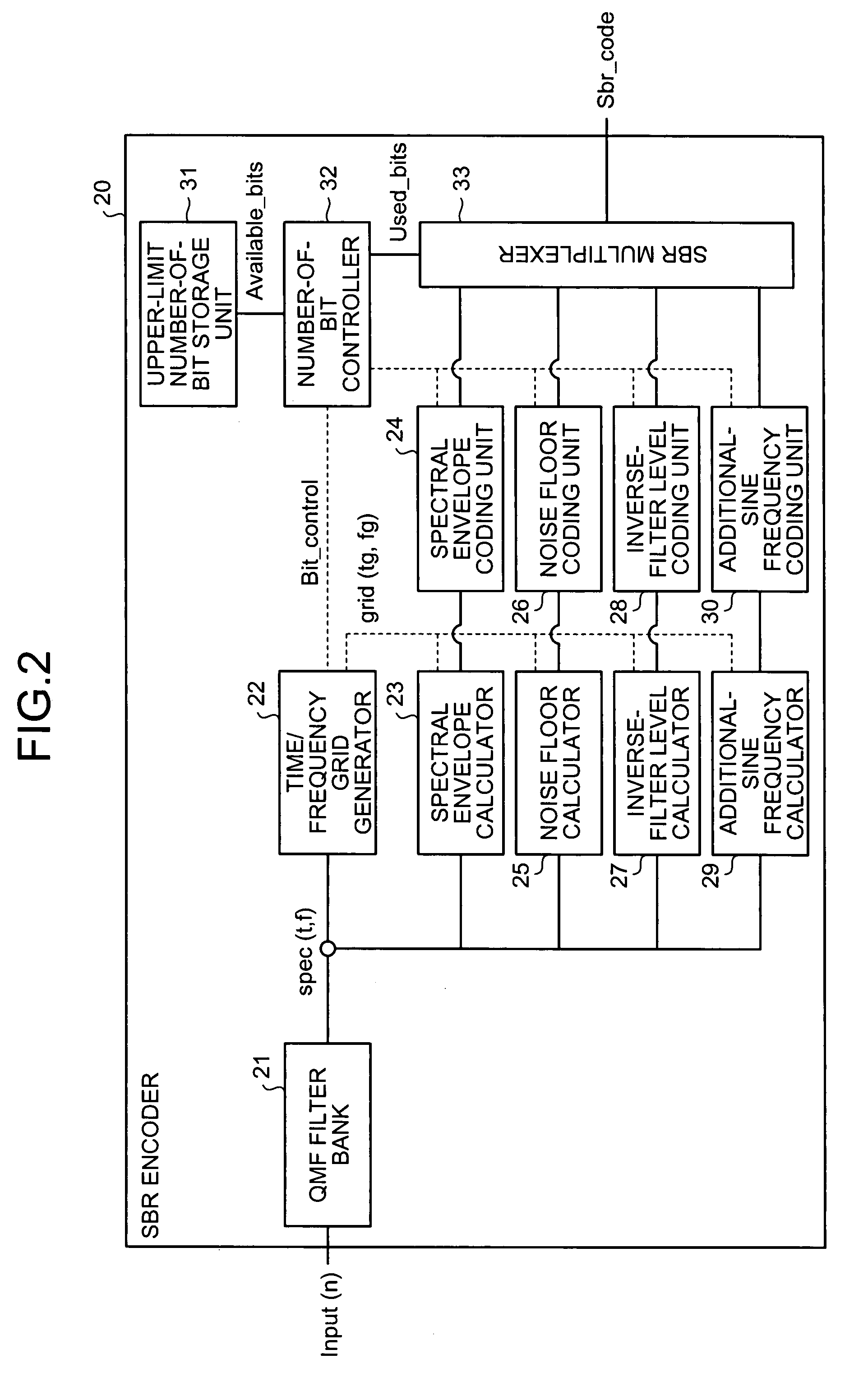
[0055] A configuration of the SBR encoder shown in FIG. 1 is explained next with reference to FIG. 2. FIG. 2 is a block diagram of the configuration of the SBR encoder according to the first embodiment. As shown in FIG. 2, an SBR encoder 20 includes a quadrature mirror filter (QMF) filter bank 21, a time / frequency grid generator 22, a spectral envelope calculator 23, a spectral envelope coding unit 24, a noise floor calculator 25, a noise floor coding unit 26, an inverse-filter level calculator...

second embodiment

[0089] Thus, according to the SBR encoder in the second embodiment, the high-pass encoding process is performed relative to the respective parameters by increasing the grid width in the time direction (by reducing the number of grids). As a result, the encoded data of high-frequency component having small number of bits can be generated, while preventing degradation of the sound quality.

[0090] Units that performs the above process is explained with reference to FIG. 2. The number-of-bit controller 32 instructs the time / frequency grid generator 22 to divide the input signal into 10 grids, and the time / frequency grid generator 22 outputs the grid information, in which the input signal is divided into 10 grids, to the respective parameter calculators. The respective parameter calculators and respective parameter coding units encode the parameter calculated based on the grid information.

[0091] Thus, according to the second embodiment, the high-pass encoding process is controlled by red...

third embodiment

[0097] Thus, the SBR encoder determines the component to be encoded and the component not to be encoded relative to each parameter as fine adjustment, thereby enabling encoding of all the parameters well under the upper limit of the number of bits. As a result, fine adjustment such as giving priority to the sound quality or to the number of bits becomes possible.

[0098] Units that perform the above process are explained with reference to FIG. 2. The number-of-bit controller 32 instructs the respective parameter calculators to encode the grids equal to or lower than “A” of the frequency grid (not to encode the grids higher than frequency “A”). The respective parameter calculators and respective parameter coding units encode the parameter calculated based on the instruction.

[0099] Thus, according to the third embodiment, by preferentially encoding the parameter belonging to the frequency component below the predetermined frequency relative to the parameters, the high-pass encoding pr...


PUM


Abstract

An SBR encoder includes a filter bank that receives an input signal, a time/frequency grid generator that controls a number of bits of various parameters, a parameter calculator that calculates various parameters, a parameter coding unit that encodes the parameters, a multiplexer that multiplexes encoded data, an upper-limit number-of-bit storage unit that stores an upper limit of the number of bit of encoded data of high-frequency component finally generated in a high-pass encoding process, and a number-of-bit controller. The number-of-bit controller controls the high-pass encoding process by preferentially encoding a parameter having a large influence to sound quality and not encoding a parameter having a small influence to the sound quality relative to a plurality of parameters, so that the number of bits of the encoded data of high-frequency component finally generated in the high-pass encoding process becomes equal to or less than the upper limit to be stored in the upper-limit number-of-bit storage unit.

Description

BACKGROUND OF THE INVENTION [0001] 1. Field of the Invention [0002] The present invention relates to an encoder that performs a high-pass encoding process in which an input signal is divided into frames formed of certain samples and calculates a plurality of parameters indicating characteristics of a high-frequency component in the input signal, thereby generating encoded data of high-frequency component. [0003] 2. Description of the Related Art [0004] Conventionally, music files and video images having a large volume are transferred via a network such as the Internet due to popularization of mobile phones, personal computers, and the like. [0005] An encoding technique for reducing the volume by compressing the music files and the like having a large volume has been used for quickly transmitting the music files and the like having the large volume, on a line with a slow transmission speed (a low bit rate). The encoding technique is also used when the music file and the like are accu...

Claims


Application Information

Patent Timeline
IPC IPC(8): G10L21/00G10L19/02G10L19/025G10L19/035G10L21/0388
CPCG10L21/038G10L19/002
Inventor TSUCHINAGA, YOSHITERUSUZUKI, MASANAOSHIRAKAWA, MIYUKIMAKIUCHI, TAKASHI
Owner FUJITSU LTD
Why Eureka
Try Eureka