
Self-regulated cooling mechanism

a heat generation device and self-regulation technology, applied in the direction of lighting and heating apparatus, instruments, and the details of the semiconductor/solid-state device, can solve the problems of loss of efficiency, performance, efficiency degradation, etc., and achieve the effect of fine control of fluid flow, and reduction of the amount of heat removed from the devi

Inactive Publication Date: 2008-05-01
IBM CORP
View PDF7 Cites 66 Cited by
  • Summary
  • Abstract
  • Description
  • Claims
  • Application Information

AI Technical Summary

Benefits of technology

[0007]In one embodiment, the invention makes use of a shape memory material to regulate the temperature of a heat-generating device within a desired range. Cooling fins are disposed in thermal contact with a heat generating device. Heat is removed by fluid flowing between the cooling fins. The fluid may be air, liquid, or a combination of air and liquid. A shape memory material, which expands and contracts in response to a stimulus, is within the path the fluid flow. At a desired low operating temperature of the heat generating device, the shape memory material will expand in response to a stimulus to restrict fluid flow, and therefore reduce the amount of heat removed from the device. At a desired high operating temperature of the heat generating device, the shape memory material will contract in response to a stimulus to allow unrestricted fluid flow, and therefore not affect the amount of heat removed from the device. The stimulus may be the temperature of the heat-generating device, or a signal generated in response to the temperature of the heat-generating device. A plurality of shape memory materials may be utilized to achieve fine control of fluid flow, with each shape memory material responding to different stimuli, or different levels of stimuli.
[0008]In another embodiment, the invention makes use of shape memory materials to regulate the temperature of multiple heat-generating devices within ranges desirable to each heat-generating device. ...

Problems solved by technology

Typically, the greatest danger to a device is overheating of components, resulting in degradation of lifespan, performance, and efficiency.
However, there may also be undesirable effects of operating below threshold temperatures, such as a loss in efficiency, or damage due to repeated thermal cycling.

Method used


Image

  • Self-regulated cooling mechanism
  • Self-regulated cooling mechanism
  • Self-regulated cooling mechanism

Examples


second embodiment

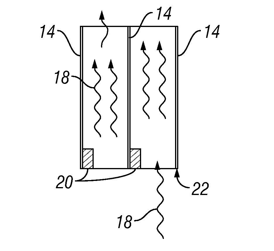
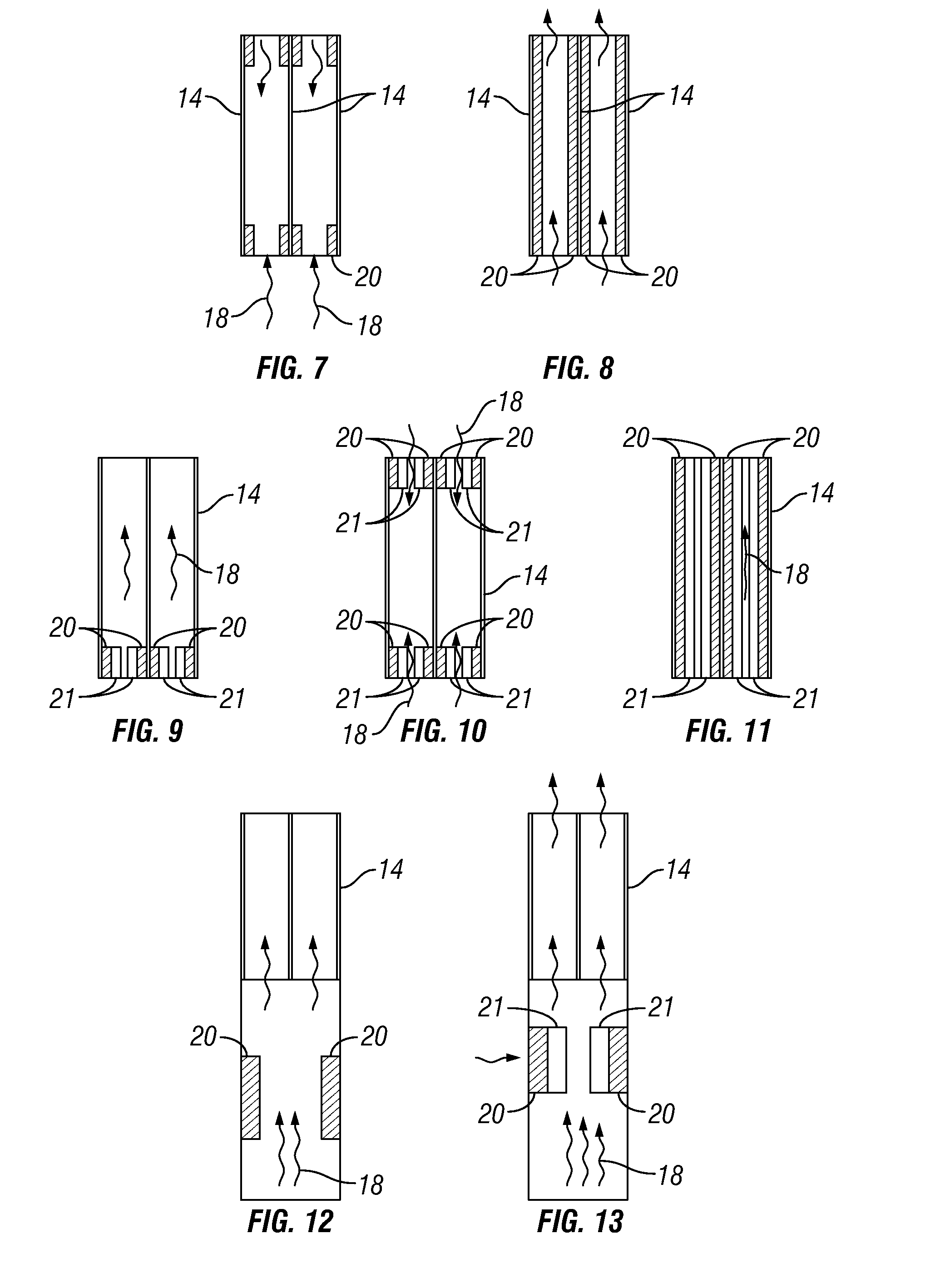
[0029]In a second embodiment, two or more shape memory materials are disposed in thermal contact with the cooling fins, effectively realizing the same temperature as the heat-generating device being protected. The two or more shape memory materials are designed or selected to expand or contract at different temperatures. A first shape memory material may expand to partially restrict the fluid flow between the cooling fins at a first specified low temperature of the heat-generating device. A second shape memory material may expand at a second specified lower temperature of the heat-generating device to further restrict the fluid flow through the cooling fins. Conversely, the first and second shape memory materials will have differing temperatures of contraction at which they do not act to restrict the fluid flow through the cooling fins. Therefore, the amount of fluid flow restricted can be carefully and passively controlled.

[0030]The shape memory material can be disposed in contact ...

third embodiment

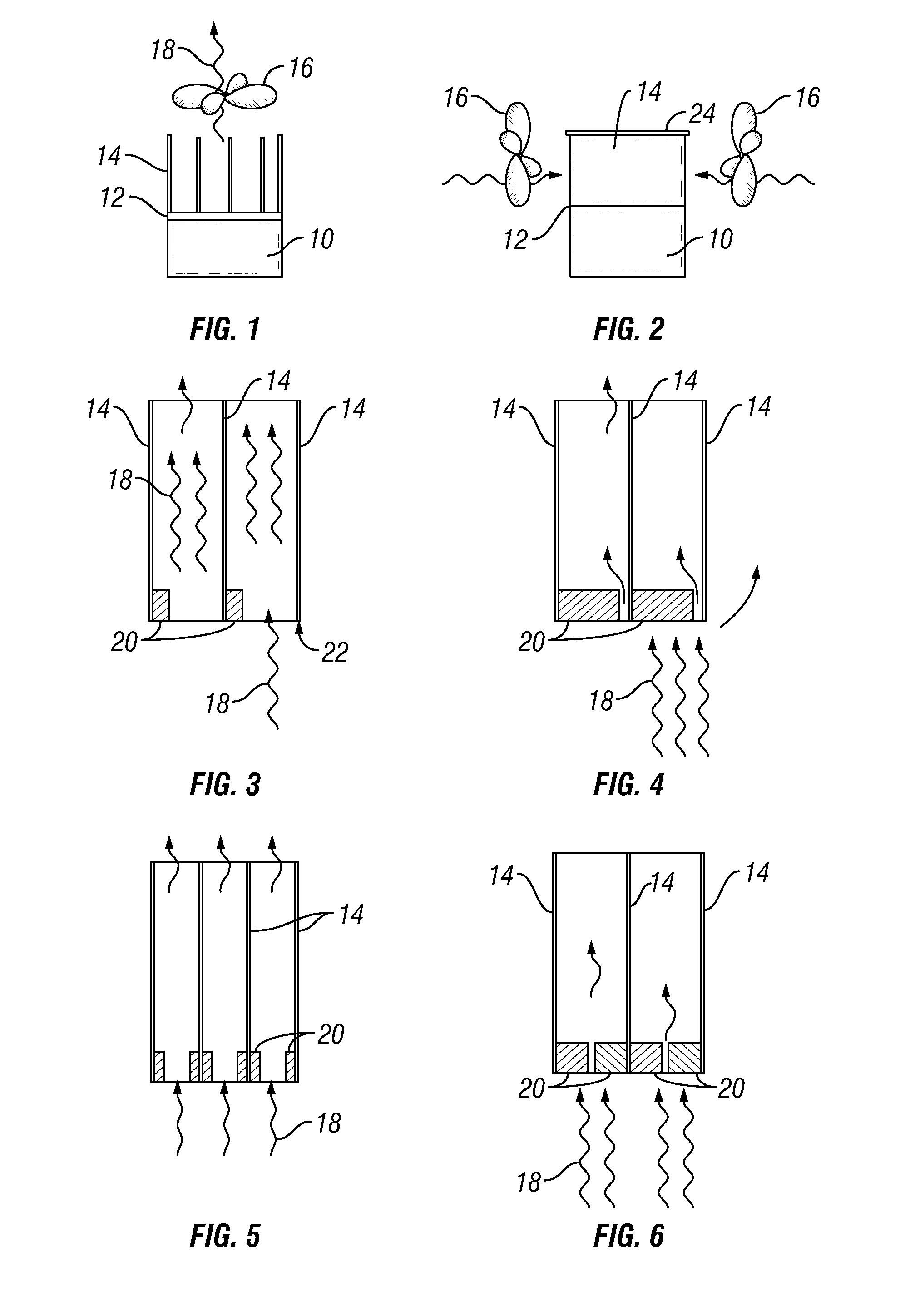
[0031]In a third embodiment, a heat-generating device has cooling fins disposed in contact to dissipate heat. The shape memory polymers are disposed in a manner to restrict fluid flow through the cooling fins. The stimulus for the shape memory material to expand or contract is supplied from an external source. While commonly used stimuli are electrical, magnetic, or thermal, any stimulus activating the shape memory material can be applied. A preferred electrical stimulus is generated and sent to the shape memory material in response to the processor detecting that the temperature of the heat-generating device is out of the desired operating range or desired operating set point. The temperature sensor may be part of a chip set that includes the processor and the processor may be the heat-generating device itself. Other temperature control schemes using the shape memory materials can be readily envisioned.

[0032]FIG. 1 is a side view of a typical heat-generating device 10 in thermal co...


PUM


Abstract

Regulating the temperature of a heat-generating device within a desired range using shape memory materials disposed on a heat sink. According to one embodiment, cooling fins are placed upon a heat-generating device. Fluid flows through the cooling fins to remove heat from the device. A shape memory material is placed within the path of fluid flow to regulate the amount of fluid flow in response to stimuli at desired low and high operating temperatures of the heat-generating device. At the low desired device operating temperature, the shape memory material restricts the amount of fluid flow through the cooling fins. At the high desired device operating temperature, the shape memory material does not restrict fluid flow through the cooling fins.

Description

BACKGROUND OF THE INVENTION[0001]1. Field of the Invention[0002]The present invention relates to regulating the temperature of a heat-generating device.[0003]2. Description of the Related Art[0004]Devices of many types have an optimum operating temperature range. For this reason, a great deal of design and engineering emphasis has been placed upon cooling, to prevent shortened component lives due to exposures to temperatures above a threshold temperature. Typically, the greatest danger to a device is overheating of components, resulting in degradation of lifespan, performance, and efficiency. However, there may also be undesirable effects of operating below threshold temperatures, such as a loss in efficiency, or damage due to repeated thermal cycling. In addition, devices must be designed to tolerate a greater range of operating temperatures when only the upper end of an operating temperature range is controlled.[0005]Many cooling configurations employ a system involving the usage ...

Claims


Application Information

Patent Timeline
IPC IPC(8): H05K7/20G05D23/00
CPCC08L2201/12F28F3/02F28F27/00G05D23/08H01L23/467H01L2924/0002F28F2255/04H01L2924/00
Inventor AKSAMIT, SLAVEK PETERMCLEAN, JAMES GORDONMEDINA, CRISTIAN
Owner IBM CORP
Features
  • Generate Ideas
  • Intellectual Property
  • Life Sciences
  • Materials
  • Tech Scout
  • Unparalleled Data Quality
  • Higher Quality Content
  • 60% Fewer Hallucinations
Learn More