
Injection molding control method

a technology of injection molding machine and control method, which is applied in the direction of recycling, recycling and recovery technologies, etc., can solve the problems of increasing device cost and difficult to obtain satisfactory products

Active Publication Date: 2008-05-01
NISSEI PLASTIC IND CO LTD
View PDF5 Cites 22 Cited by
  • Summary
  • Abstract
  • Description
  • Claims
  • Application Information

AI Technical Summary

Benefits of technology

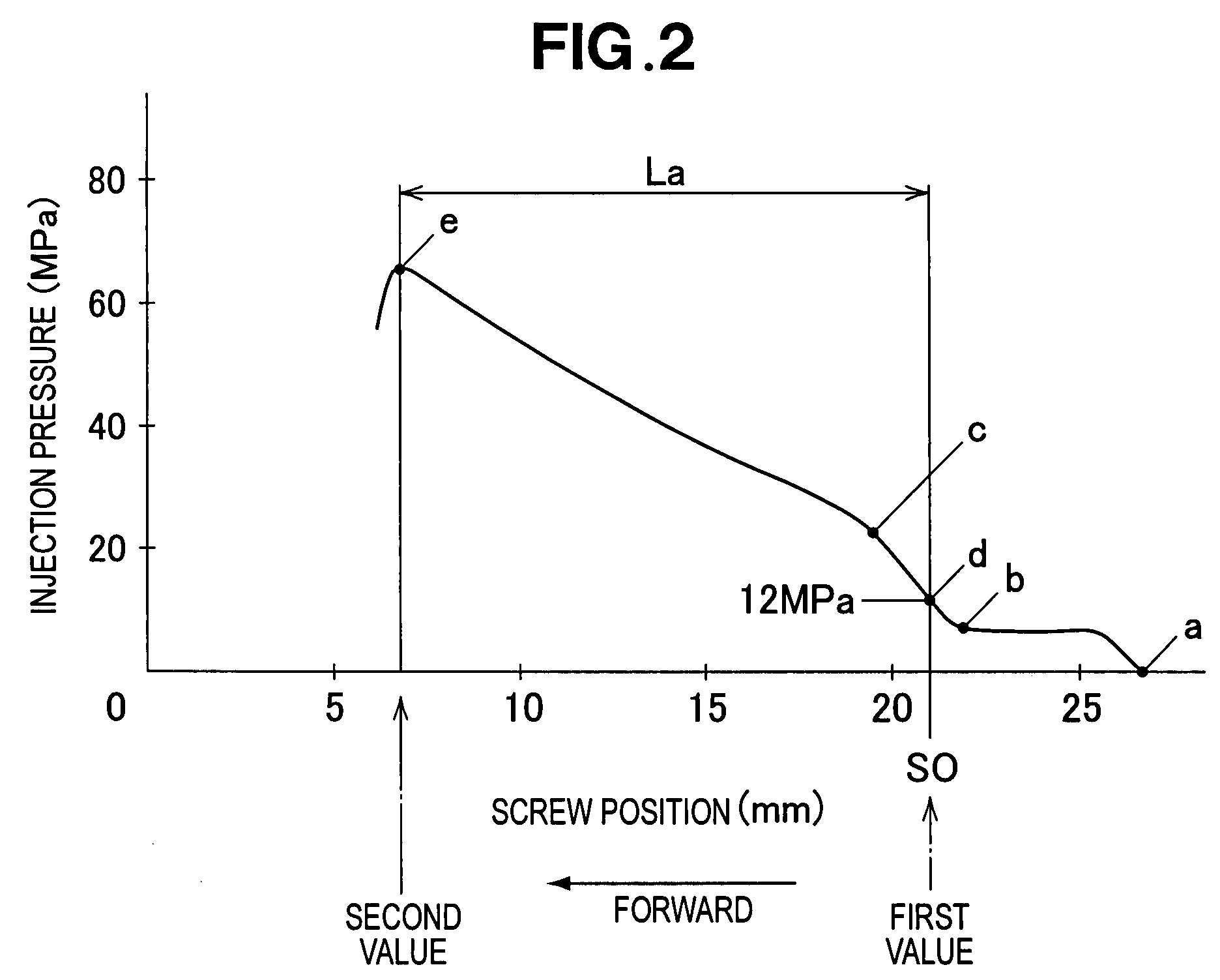
The present invention provides an injection molding method that can predict injection conditions by using a neural network, and can take into account multiple fluctuating factors such as temperature and pressure. The method allows for high-speed molding and can easily improve the quality of the manufactured product. The method includes acquiring measurement monitor values during test injection molding and using them to determine the prediction function. The prediction function is then used to predict the first value, which is used as the injection condition. The second value is determined based on the first value and is used for pressure maintenance control. The method can be implemented in a conventional injection molding machine without increasing the computation speed or cost. The measurement monitor values can include various factors such as starting position, cycle time, and heating cylinder temperature. The accuracy of the injection conditions can be monitored by comparing the predicted first value with the injection monitor value at the end of the injection step.

Problems solved by technology

The sequence of operations described above is difficult to perform in such a short time, and even if these operations could be performed, a high-sensitivity sensor or a control unit capable of performing high-speed computation is necessary, and device costs increase.
In this configuration, a satisfactory product becomes difficult to obtain when the temperature of the heating cylinder, the cycle time, and other factors fluctuate.

Method used


Image

  • Injection molding control method
  • Injection molding control method
  • Injection molding control method

Examples


Embodiment Construction

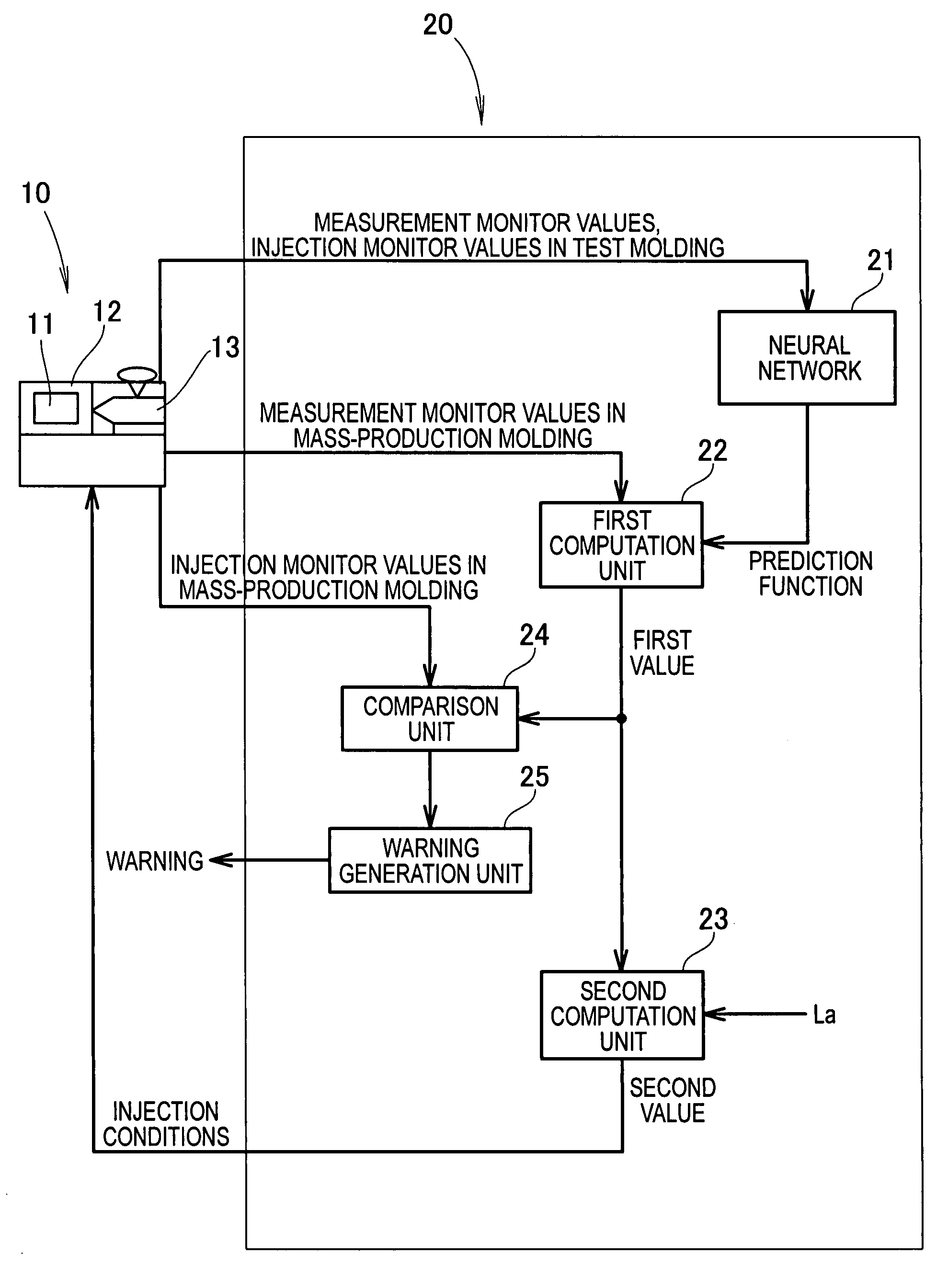
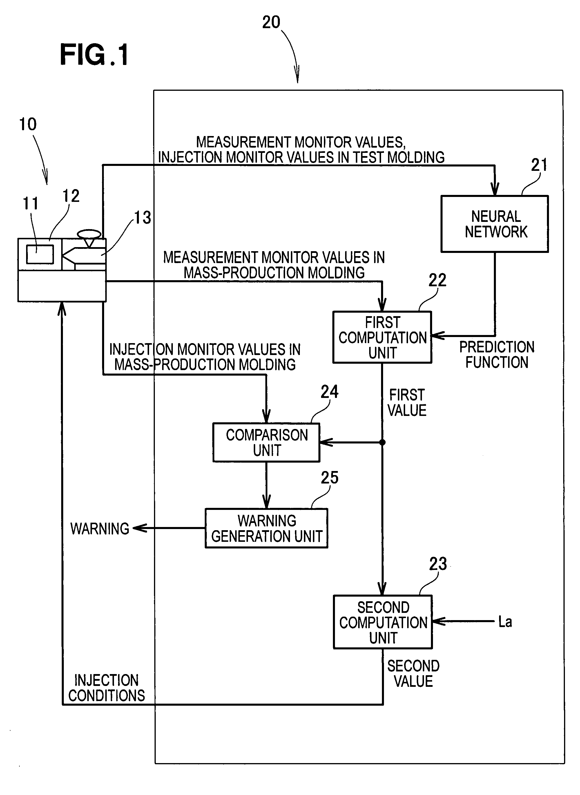
[0043]As shown in FIG. 1, the injection molding machine 10 is basically comprised of a mold clamping device 12 for clamping a die 11, and an injection device 13 for injecting a resin into the die 11. The injection molding machine 10 is provided with a control device 20 that includes a neural network.

[0044]The control device 20 includes a neural network 21 for incorporating a measurement monitor value and an injection monitor value of a test molding performed by the injection molding machine 10 and generating a prediction function; a first computation unit 22 for computing a first value on the basis of the prediction function generated by the neural network 21, and the measurement monitor value of a mass-production molding performed by the injection molding machine 10; a second computation unit 23 for computing a second value that corresponds to injection conditions on the basis of the first value that was computed by the first computation unit 22; a comparison unit 24 for comparing ...


PUM

PropertyMeasurementUnit
temperatureaaaaaaaaaa

Abstract

An injection molding control method that uses a neural network is disclosed. The control method determines an injection condition according to a prediction function, a first value, and a second value. The prediction function is implemented in test molding, and the first value and second value are implemented in a measurement step that has a time margin. The injection condition predicted for mass-production molding is determined prior to the injection step, and the need for computation during the injection step is thereby eliminated.

Description

FIELD OF THE INVENTION[0001]The present invention relates to a method for controlling an injection molding machine through the use of a control device that includes a neural network.BACKGROUND OF THE INVENTION[0002]The quality of a product obtained in an injection molding machine for producing a product by performing a plasticizing / measurement process (hereinafter referred to as a measurement process) and an injection / pressure maintenance process (hereinafter referred to as an injection process) is dependent on the injection conditions, and it is therefore important that the injection conditions be adjusted so that a satisfactory product is obtained.[0003]The injection conditions include V-P switching control for switching the screw control from speed control to pressure control, and a technique for obtaining a satisfactory product by correcting the V-P switching position is disclosed in JP 2005-335078 A.[0004]The injection conditions during the abovementioned injection molding will...

Claims


Application Information

Patent Timeline
Patent Type & Authority Applications(United States)
IPC IPC(8): B29C45/80
CPCB29B17/00B29C2945/76979B29C45/7613B29C45/76Y02W30/62
Inventor YAMAGIWA, YOSHITOSHISHIOIRI, TAKAYOSHIIWASHITA, EIKI
Owner NISSEI PLASTIC IND CO LTD
Learn More