Hold time error correction method and correction program for integrated circuits

a technology of integrated circuits and hold time errors, which is applied in the direction of cad circuit design, generating/distributing signals, instruments, etc., can solve the problems of increasing difficulty in layout while checking signal timing, easy to delay the timing of data data by inserting a delay buffer, and difficult to advance the timing of data data

Inactive Publication Date: 2006-01-24
SOCIONEXT INC
View PDF10 Cites 23 Cited by
  • Summary
  • Abstract
  • Description
  • Claims
  • Application Information

AI Technical Summary

Benefits of technology

[0027]According to the above invention, a hold time error list, having for each hold time error path a hold time error value satisfying a plurality of timing constraints, and more specifically a maximum hold time error value for each of the timing constraints, as well as a setup time margin map which allocates to path on the integrated circuit a setup time margin satisfying a plurality of timing constraints for each setup time error path, and more specifically minimum value of setup time margins for the same path for each timing constraint, are generated. Also, referring to this setup time margin map, delay buffer, which reduces or eliminates the hold time error of the hold error list, and a delay of which is within the range of delay amounts and positions equal to or lower than the setup time margin, are inserted. By referring to the setup time margin map, it is possible to insert delay buffer to correct the hold time error without causing new setup time errors.
[0028]In a preferred embodiment, a plurality of delay buffers are inserted, and each time one delay buffer is inserted, the setup time margin within the setup margin map is updated according to the delay amount and position of the delay buffer; when inserting the next delay buffer, this updated setup time margin map is referenced. That is, the delay amount is subtracted from the setup time margin of the path in which the delay buffer is inserted, to update the setup time margin map. By this means, a plurality of delay buffers can be inserted in sequence within the ranges of the setup time margin in the setup margin map, so that a plurality of delay buffers can be inserted without causing any new setup time errors.

Problems solved by technology

As the logic circuitry within semiconductor integrated circuit chips has increased in scale and moved to higher speeds, it has become increasingly difficult to perform layout while checking signal timing.
After layout of the logic circuit, however, it is difficult to advance the timing of the data DATA.
On the other hand, the later the end of the data DATA, the more easily the hold time HT requirement can be met; but even after completion of the logic circuit layout, it is easily to delay this timing by inserting a delay buffer.
For example, if the process conditions fluctuate toward poorer conditions (characteristics become slower), the power supply voltage fluctuates toward lower voltages, and the operating temperature fluctuates toward higher temperatures, then the circuit delay will increase, and operating speed will be slowed.
If the above setup time requirement is not satisfied, a setup time error or violation (hereafter simply “setup error”) occurs, and if the hold time requirement is not satisfied, a hold time error or violation (hereafter simply “hold error”) occurs.
It is difficult to modify the layout to advance the timing after the layout is completed.
However, this hold error correction has the following problems.
First, if a delay buffer is inserted in order to correct a hold error, a hold error for one type of timing constraint inputted to the layout tool is corrected; but if timing analysis is performed for another timing constraint, a new setup error may occur for the signal path.
Once a setup error occurs, correction of the setup error is difficult, nor is it an easy matter to decide where a delay buffer should be inserted.
As a result, signals on a signal path which share the signal path into which the delay buffer was inserted are also delayed, so that for example in the case of the Q3-D2 signal, the setup time ST is shortened, possibly causing a setup error.
If a delay buffer is inserted between the flip-flop FF1 and the AND gate, the Q1-D4 signal is also affected, and in similar fashion a setup error may occur.
As a second problem, in the case of a plurality of timing constraints corresponding to a plurality of operating modes, the hold times and setup times will be different, and correction of hold errors so as to satisfy all these conditions becomes extremely complicated.
As a result, automatic correction of hold errors by computer is no longer possible, and ordinarily manual correction is performed by a skilled designer.
In this way, when correcting timing errors, if layout is performed with priority given to the setup time and hold errors are then corrected, there is no method for inserting delay buffers without causing new setup errors, nor is there a method for inserting delay buffers to correct a hold error for a given timing constraint while preventing the occurrence of new setup errors under different timing constraints, and so the automatic correction of hold errors by a computer has been impossible.

Method used


Image

  • Hold time error correction method and correction program for integrated circuits
  • Hold time error correction method and correction program for integrated circuits
  • Hold time error correction method and correction program for integrated circuits

Examples


modified example 1

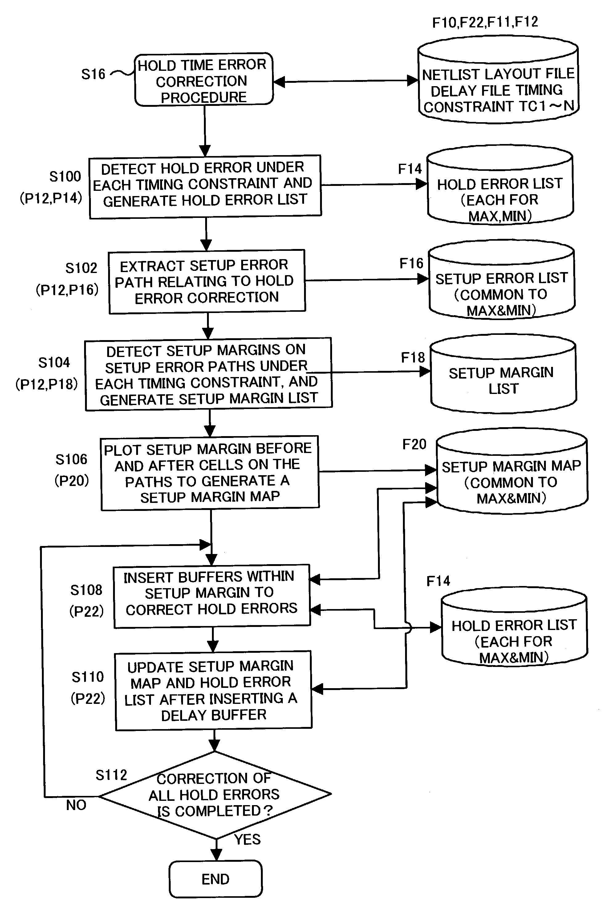
[0131]In the above embodiment, during the procedure S102, paths which have at least a portion in common with hold error paths were extracted as paths which are affected when a delay buffer is inserted to correct a hold error (related setup error paths). By this means, the scale of the setup margin map could be made an appropriate size.

[0132]In one modified example, when it is difficult to extract paths having at least a portion in common with the above hold error paths, the following method may be used instead to extract the related setup error paths. The largest hold error value is extracted from the error values of the hold error list, and it is determined, when a delay buffer with this error value is inserted, how much of a delay amount is added using the MAX delay characteristic. Of the setup margins determined using each timing constraint, those paths having setup margins equal to or less than the delay amount for the above MAX condition are then extracted as setup error paths....

modified example 2

[0134]In this modification, a prescribed margin is subtracted from the margin values of the setup margin map. In the above-described embodiment, if the delay value at the MAX delay characteristic of the inserted cell is equal to or less than the minimum setup margin, insertion at that position is permitted. However, in consideration of computation errors of the STA tool, the margin values of the setup margin map are set to, for example, approximately 20% lower. Or, when the delay value at the MAX delay characteristic of the inserted cell is equal to or less than 80% of the minimum setup margin value, insertion at that position may be permitted. By this means, even if there is some degree of error in the setup margin calculations, the occurrence of new setup errors can be reliably avoided.

[0135]In particular, in the layout process shown in FIG. 4, there is the possibility that the layout processing of a delay cell inserted in the procedure S16 to insert a delay cell for correction of...

modified example 3

[0136]In the specific example of FIG. 9 through FIG. 22, the hold error list is subjected to error correction using the MIN delay characteristic as shown in FIG. 10. Hence only setup error paths related to hold error paths for this MIN delay characteristic are extracted. When the hold error list also includes errors at the MAX delay characteristic, setup error paths related to such MAX-side hold error paths must also be extracted, and the setup margins of these paths added to the setup margin map. Hence even if the MAX delay characteristic hold error list is added, only a single type of setup margin map is sufficient.

[0137]Creation of the hold error list is similar for the MAX delay characteristic and the MIN delay characteristic. When selecting candidate delay cells for insertion, the hold errors for the MIN delay characteristic are given priority for correction. Hold errors occurring for the MIN delay characteristic (high-speed operation) are more numerous, so that by giving these...


PUM


Abstract

A hold time error list, having for each hold time error path a hold time error value satisfying plural timing constraints, and more specifically a maximum hold time error value for each of timing constraints, as well as a setup time margin map allocating to path a setup time margin satisfying plural timing constraints for each setup time error path, and more specifically minimum value of setup time margins for the same path for each timing constraint, are generated. Also, referring to this setup time margin map, delay buffers, which reduces or eliminates hold time error of hold error list, and a delay of which is within the range of delay amounts and positions equal to or lower than the setup time margin, are inserted. Referring to the setup time margin map, it is possible to insert delay buffer to correct hold time error without causing new setup time errors.

Description

BACKGROUND OF THE INVENTION[0001]1. Field of the Invention[0002]This invention relates to a method for correction of hold time errors for LSI logic circuits (integrated circuits) and a program for same, and in particular relates to a hold time error correction method and program which satisfies all of a plurality of timing constraints corresponding to a plurality of operating modes. Moreover, this invention provides a layout method and program which do not generate timing errors under a plurality of timing constraints. The hold time error is sometimes called as a hold time violation. In this specification, “hold time error” or “hold error” is commonly used as the hold time violation.[0003]2. Description of the Related Art[0004]As the logic circuitry within semiconductor integrated circuit chips has increased in scale and moved to higher speeds, it has become increasingly difficult to perform layout while checking signal timing. Conventional layout tools are programs which perform la...

Claims


Application Information

Patent Timeline
Patent Type & Authority Patents(United States)
IPC IPC(8): G06F17/50G06F1/10G06F1/12H01L21/82
CPCG06F17/5068G06F17/505G06F30/39G06F30/327G06F30/3315
Inventor YOSHIKAWA, SATORU
Owner SOCIONEXT INC
Why Eureka
Try Eureka