Insertion-Type Light Source Device

a light source and light source technology, applied in the direction of semiconductor devices, light sources, lighting and heating devices, etc., can solve the problem of unnecessary calibration, achieve the effect of reducing the dim area, greatly enhancing the light utilization efficiency, and increasing the electroplated area of the reflector

Inactive Publication Date: 2008-05-01
KTO TECH
View PDF0 Cites 1 Cited by
  • Summary
  • Abstract
  • Description
  • Claims
  • Application Information

AI Technical Summary

Benefits of technology

[0012]A further objective of the present invention is to provide an insertion-type light source device, wherein the light source includes a handle for facilitating the replacement so that the whole device will not be contaminated.
[0013]A still further objective of the present invention is to provide an insertion-type light source device, in which an axis of the light emitted by the light source is perpendicular to the filament tube to eliminate the dim area in a center of projection area.
[0014]An even further objective of the present invention is to provide an insertion-type light source device, in which two electrodes are at the same end of the tube. Due to only one opening being provided for insertion of the light source, an electroplated area of a reflector is increased. The light utilization efficiency is greatly enhanced. In addition, because the two reflectors are integrally molded, the calibration is unnecessary when reassembled. The manufacturing cost is reduced as well.

Problems solved by technology

In addition, because the two reflectors are integrally molded, the calibration is unnecessary when reassembled.

Method used


Image

  • Insertion-Type Light Source Device
  • Insertion-Type Light Source Device
  • Insertion-Type Light Source Device

Examples


first embodiment

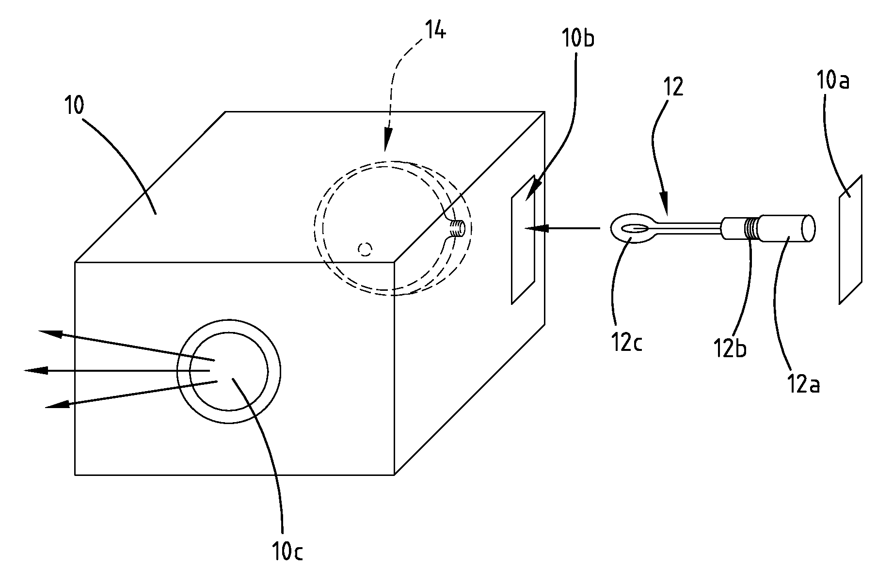
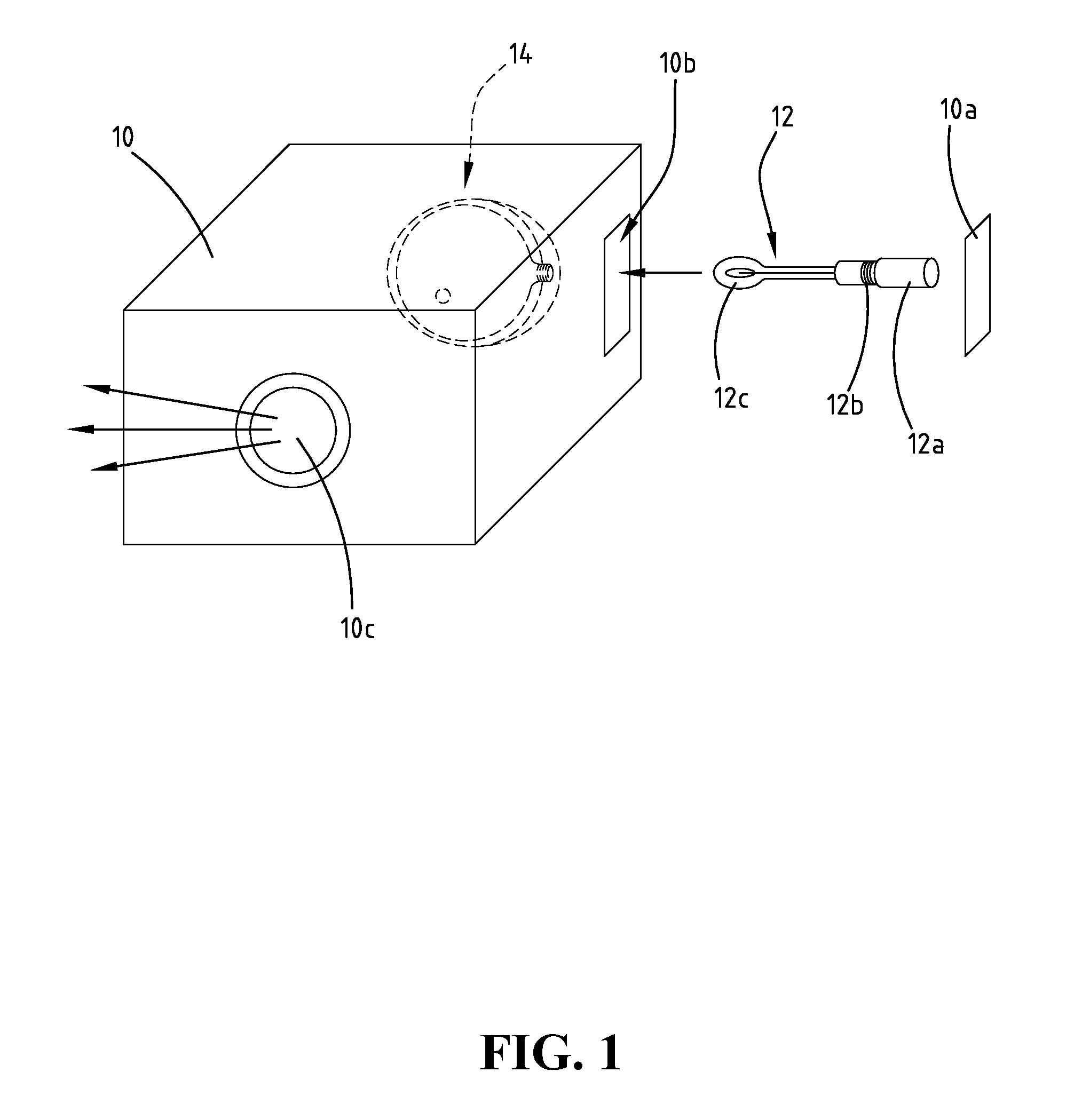
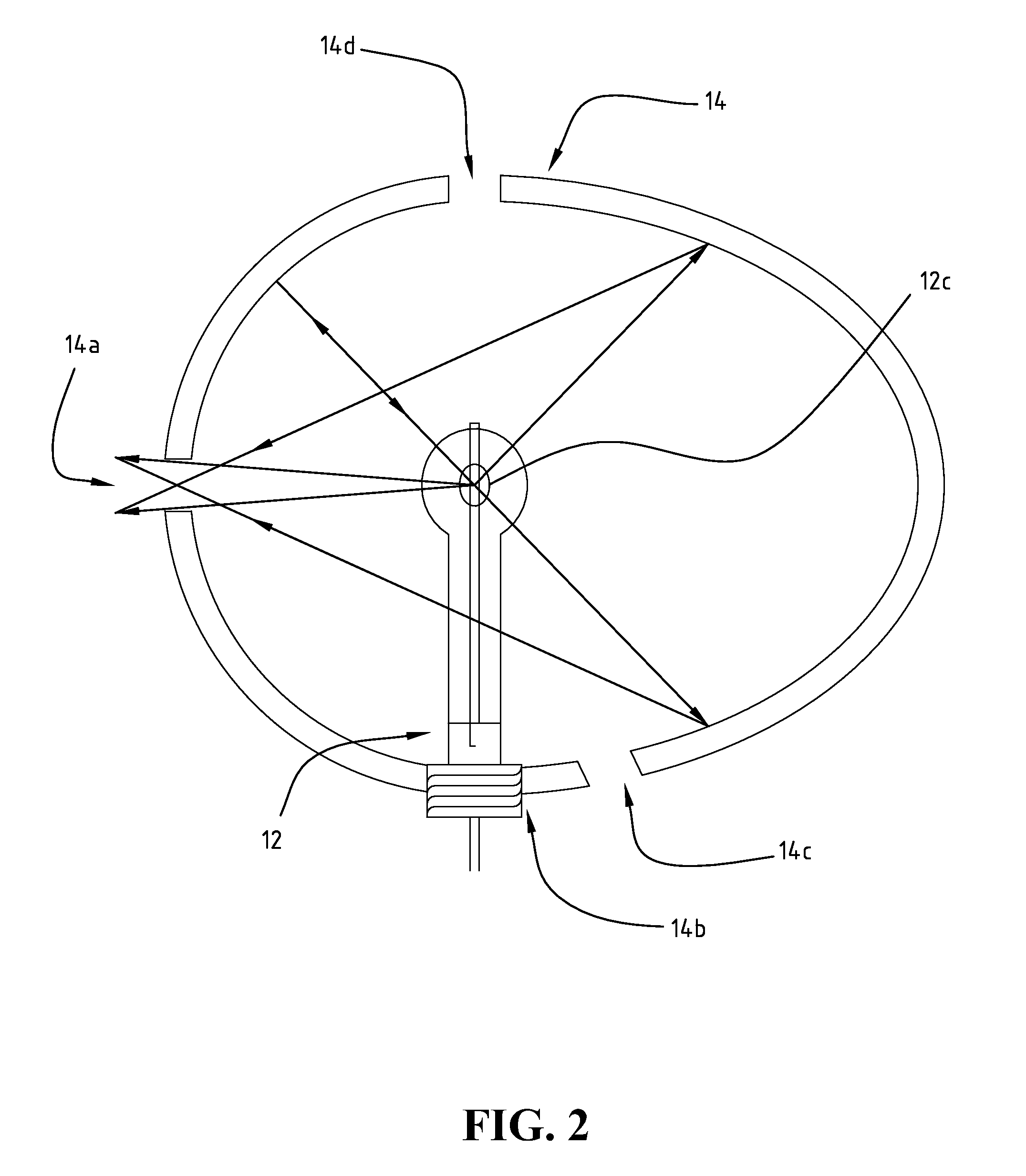
[0025]With reference to FIG. 2, an insertion-type light source device in accordance with the present invention comprises a light source 12 and an envelope 14. The envelope 14, which is an integrally molded hollow body composed of at least two concave reflectors, has a light outlet 14a to let light pass through and an opening 14b for inserting the light source 12 into an interior of the envelope 14. Vents 14c and 14d may be further provided on the envelope 14, which serve as outlet for air and enhance the heat dissipation efficiency.

[0026]When the light source 12 is installed, a user holds the handle 12a of the light source 12 to pass through the opening 14b and insert the light source 12 into the interior of the envelope 14. After the filament 12c is completely inserted into or screwed into the envelope 14, the filament 12c approximately aligns with the light outlet 14a and the projector lens 10c. On the other hand, when the light source 12 is replaced, the user holds the handle 12a...

second embodiment

[0031]With reference to FIG. 3, an insertion-type light source device in accordance with the present invention comprises a light source 12 and an envelope 15. The envelope 15 composed of a concave reflector 15a in conjunction with an elliptical reflector 15b, has a light outlet 14a provided on the concave reflector 15a, and an opening 14b provided between the concave reflector 15a and the elliptical reflector 15b. To enhance the heat dissipation efficiency, vents 14c and 14d may be further included in the envelope 15.

[0032]When the light source 12 is installed with the envelope 15, the user can hold a handle 12a of the light source 12 to insert the light source 12 into the interior of the envelope 15 through the opening 14b. After a filament 12c is completely inserted into the envelope 15, the filament 12c approximately aligns with the light outlet 14a

[0033]The difference between the first embodiment and the second embodiment is that the elliptical reflector 15b used in the second ...

third embodiment

[0035]With reference to FIG. 4, an insertion-type light source device in accordance with the present invention comprises a light source 12 and an envelope 16. The envelope 16 is composed of a concave reflector 16a and a planar reflector 16b. The planar reflector 16b has an elliptical reflector 16c recessed at a center thereof. A light outlet 14a is provided on the concave reflector 16a, and an opening 14b is provided between the concave reflector 16a and the planar reflector 16b. To enhance the heat dissipation effect, the envelope 16 may further include vents 14c and 14d. When the light source 12 is working, the light is reflected by the elliptical reflector 16c, which is very close to the filament 12c, and projected out through the light outlet 14a.


PUM

PropertyMeasurementUnit
insulatingaaaaaaaaaa
transparentaaaaaaaaaa
colorsaaaaaaaaaa

Abstract

An insertion-type light source device comprises a light source having a filament mounted on a base and a handle extended from the base, and an envelope, which is an integrally molded hollow body composed of at least two concave reflectors, having a light outlet and an opening for inserting the filament of the light source into an interior of the envelope. The light source is replaceable by means of removing the light source from the envelope through the opening. After the light source is completely inserted, the light source is positioned correctly relative to the reflectors of the envelope without calibration. In use, a user can hold the handle of the light source to prevent the whole device from contamination.

Description

BACKGROUND OF THE INVENTION[0001]1. Field of the Invention[0002]The present invention relates to an insertion-type light source device, and in particular to an insertion-type light source device which is easy to assemble and position the filament in an envelope, and has high light delivery efficiency and low contamination.[0003]2. The Prior Arts[0004]Basically, the principle of a projection displayer is similar to that of all projectors. The projector casts light on an image-displaying component to generate images, and then the images are projected through a lens onto a screen. The image-displaying component includes two types: a transmissive type which lets light pass through a transparent piece to project the resulting image onto the screen, and a reflective type which shines the light on an object to project the resulting image onto the screen. Both types split the light into red, green and blue, and then generate images of various colors. Because one component can display only o...

Claims


Application Information

Patent Timeline
Patent Type & Authority Applications(United States)
IPC IPC(8): H01K1/26
CPCF21V7/0033F21V7/09F21V7/22F21V19/04F21Y2101/02F21Y2101/025F21V29/83G03B21/2066G03B21/2006F21V7/08G03B21/2093G03B21/2046G03B21/16F21V7/28F21Y2115/10F21Y2115/30G03B21/20
Inventor OU-YANG, MANGHUANG, SHIH-WEI
Owner KTO TECH
Why Eureka
Try Eureka