Rotation angle detecting device

a detection device and rotating object technology, applied in the direction of measuring devices, magnetic measurements, instruments, etc., can solve the problem of difficult detection of accurate rotation angle of rotating objects

Inactive Publication Date: 2008-05-01
DENSO CORP
View PDF4 Cites 20 Cited by
  • Summary
  • Abstract
  • Description
  • Claims
  • Application Information

AI Technical Summary

Benefits of technology

[0016]In one of the above defined rotation angle detecting devices, the rotation angle calculating means may correct an offset of the output signals before calculating the phase difference or make the output signals the same amplitude before calculating the phase difference. The phase difference may be updated after the magnitude of the output signals becomes a preset value certain times or a certain time after the magnitude of the output signals becomes a preset value.

Problems solved by technology

However, if the phase difference between the output signals varies, it is difficult to detect an accurate rotation angle of the rotating object.

Method used


Image

  • Rotation angle detecting device
  • Rotation angle detecting device
  • Rotation angle detecting device

Examples


first embodiment

[0028]A rotation angle detecting device 10 according to the invention will be described with reference to FIGS. 1-5 and FIGS. 6A, 6B, 6C.

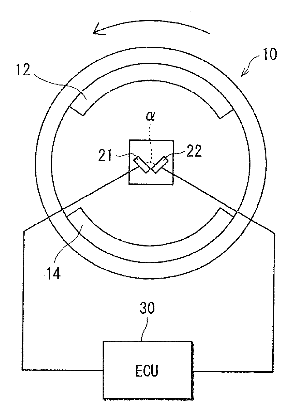
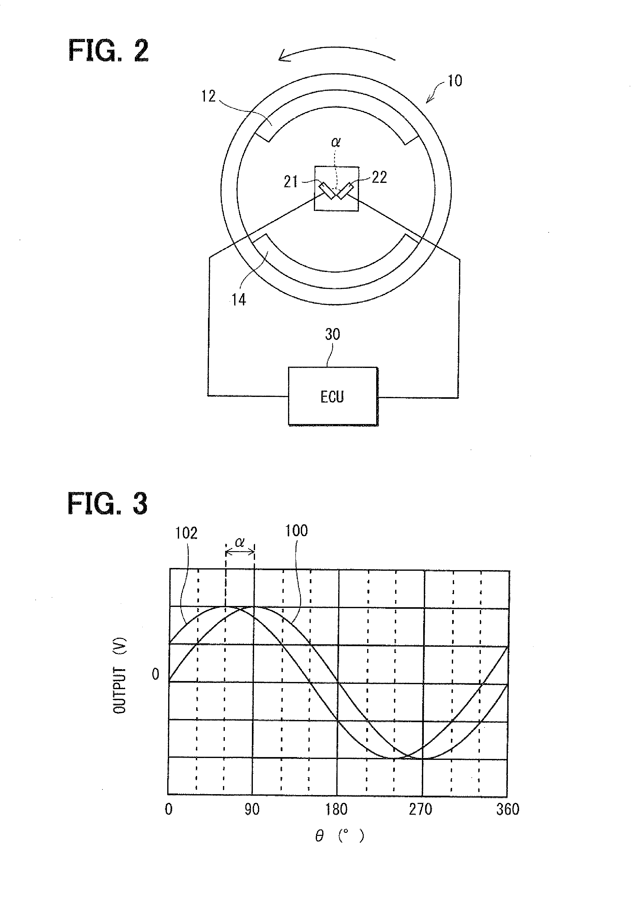
[0029]The rotation angle detecting device 10 according to the first embodiment is a device for detecting rotation angle of an engine crankshaft of a vehicle or a steering wheel thereof. As shown in FIG. 2, the rotation angle detecting device 10 includes a pair of permanent magnets 12 and 14, a pair of Hall elements 21 and 22 and an electronic control unit 30 (hereinafter referred to the ECU 30). The Hall elements 21, 22 and the ECU 30 are formed in a unit. However, they can be separated from each other.

[0030]The permanent magnets 12, 14 form a magnetic field forming member that provides a parallel magnetic field of a uniform magnetic flux density and rotates together with a rotating object. The Hall elements 21, 22 incline to each other at an angle a to form a magnetic sensor, which is connected to the ECU 30 to be operated thereby. The ECU 30 has ...

second embodiment

[0064]A rotation angle detecting device 210 according to the invention will be described with reference to FIG. 7. Incidentally the same reference numeral as the precedent embodiment represents the same or substantially the same portion, part or component as the precedent embodiment, hereafter.

[0065]The rotation angle detecting device 210 according to the second embodiment is a device for detecting rotation angle of an engine crankshaft of a vehicle or a steering wheel thereof. As shown in FIG. 7, the rotation angle detecting device 210 includes a disk-shaped permanent magnet 212, a Hall IC 220 and the ECU 30.

[0066]The permanent magnet 212 is magnetized in a diametric direction thereof. The permanent magnet has a rotary shaft 250 that rotates together with a rotating object. The Hall IC 220 is disposed radially or axially outside the permanent magnet 212 to confront the same. The Hall IC 220 is a one chip IC that includes a pair of Hall elements 221 and 222. Each of the Hall element...

third embodiment

[0067]A rotation angle detecting device 310 according to the invention will be described with reference to FIG. 8.

[0068]The rotation angle detecting device 310 includes a disk-shaped permanent magnet 212, a pair of Hall elements 321, 322 and the ECU 30.

[0069]The Hall elements 321, 322 are disposed away from each other at portions along the periphery of the permanent magnet 212. The Hall IC 220 is a one chip IC that includes a pair of Hall elements 221 and 222. Each of the Hall elements 221, 222 has a sensing surface that inclines to the other at an angle α. The sensing surface also incline to the center axis 252 of the rotary shaft so that the output voltage signals of the Hall elements 221, 222 respectively change in sinusoidal curves when a rotating object rotates, as the Hall elements 21, 22 of the first embodiment.

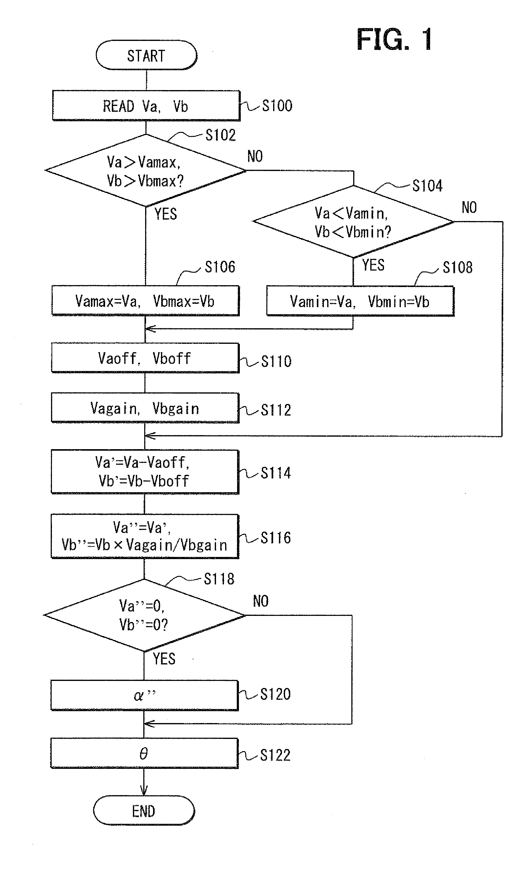
[0070]In the preceding embodiments, the phase difference α″ is updated every time the output voltage signals become a preset magnitude. The phase difference α″ can be ...


PUM


Abstract

A rotation angle detecting device includes a permanent magnet member, a pair of magnetic sensor elements disposed in a magnetic field formed by the permanent magnet member to provide a pair of output voltage signals when the magnetic field changes as the rotating object rotates; and a rotation angle calculating unit. The rotation angle calculating unit calculates a phase difference between the pair of output voltage signals from a magnitude of the output signal of one of the magnetic sensor elements when detecting a specific magnitude of the output signal of the other magnetic sensor elements whose phase angle is known.

Description

CROSS REFERENCE TO RELATED APPLICATION[0001]The present application is based on and claims priority from Japanese Patent Application 2006-291157, filed Oct. 26, 2006, the contents of which are incorporated herein by reference.BACKGROUND OF THE INVENTION[0002]1. Field of the Invention[0003]The present invention relates to a rotation angle detecting device that detects a rotation angle of a rotating object.[0004]2. Description of the Related Art[0005]JP-2003-75108-A discloses a rotation angle detecting device that includes a pair of magnetic sensors and a magnetic field forming member When a rotating object rotates, the pair of magnetic sensors of such a rotation angle detecting device is arranged to rotate relative to a magnetic field formed by the magnetic field forming member, thereby providing a pair of output signals, which is converted into a rotation angle of the rotating object.[0006]However, if the phase difference between the output signals varies, it is difficult to detect ...

Claims


Application Information

Patent Timeline
Patent Type & Authority Applications(United States)
IPC IPC(8): G01B7/30
CPCG01D5/145
Inventor MATSUMOTO, KOUICHIROUKAWASHIMA, TAKASHIKITANAKA, TATSUYA
Owner DENSO CORP
Why Eureka
Try Eureka