Image Display Device, Image Display Method, Image Display Program, Recording Medium Containing Image Display Program, and Electronic Apparatus

a technology of image display and image display program, which is applied in the direction of instruments, color signal processing circuits, computing, etc., can solve the problems of image quality possibly decreasing, and the saturation of display images possibly decreasing when the electric power consumed by a light source is reduced

Inactive Publication Date: 2008-05-01
SEIKO EPSON CORP
View PDF12 Cites 45 Cited by
  • Summary
  • Abstract
  • Description
  • Claims
  • Application Information

AI Technical Summary

Problems solved by technology

However, in the technology described in the above JP-A-2004-246099, image quality may possibly decrease due to a decrease in saturations of a display image even when apparent brightness is not changed.
In addition, in the technology described in the above JP-A-2004-54250 as well, saturations of a display image may possibly decrease when electric power consumed by a light source is reduced.

Method used


Image

  • Image Display Device, Image Display Method, Image Display Program, Recording Medium Containing Image Display Program, and Electronic Apparatus
  • Image Display Device, Image Display Method, Image Display Program, Recording Medium Containing Image Display Program, and Electronic Apparatus
  • Image Display Device, Image Display Method, Image Display Program, Recording Medium Containing Image Display Program, and Electronic Apparatus

Examples


first embodiment

[0038]A first embodiment of the invention will be described with reference to the drawings.

General Configuration

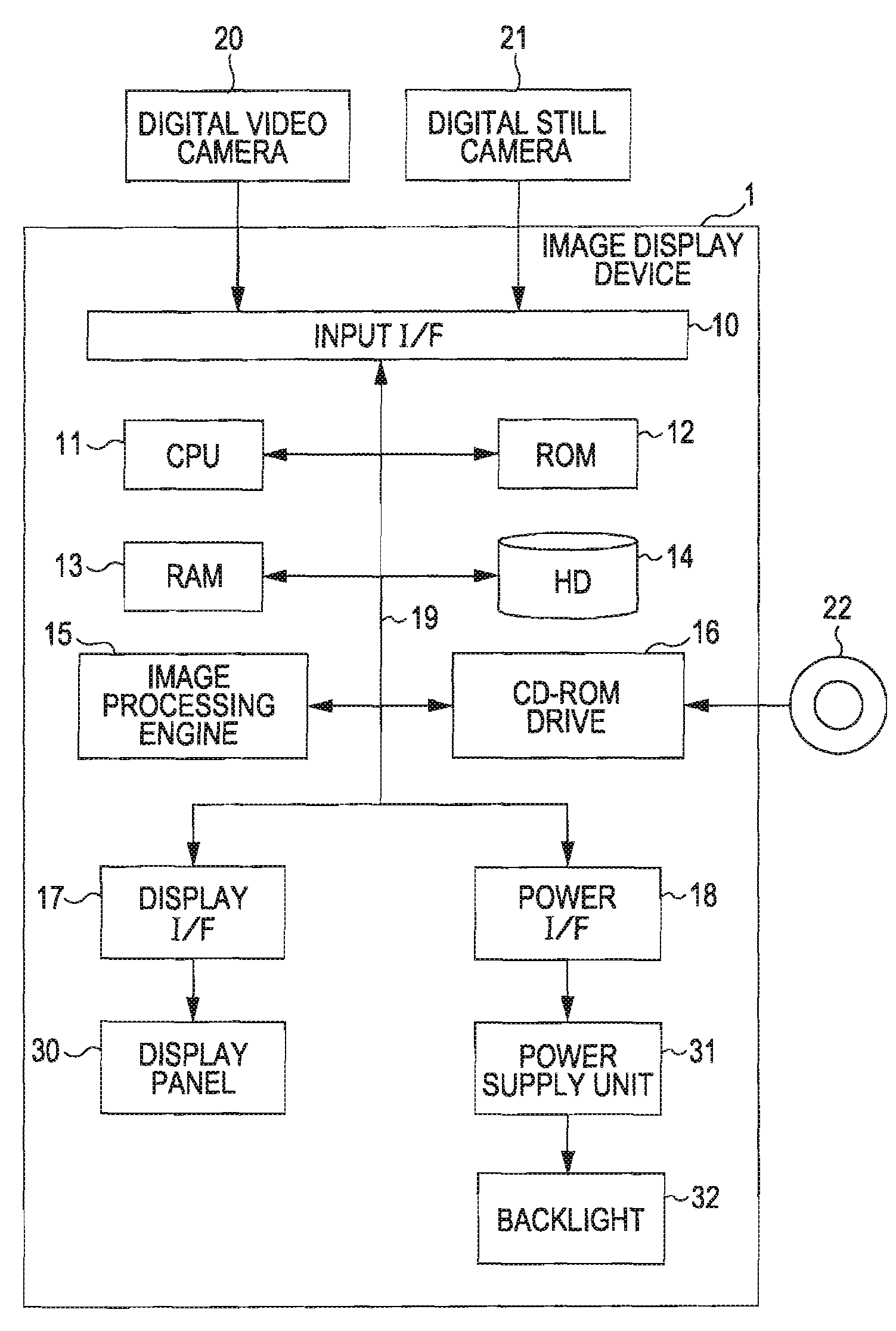
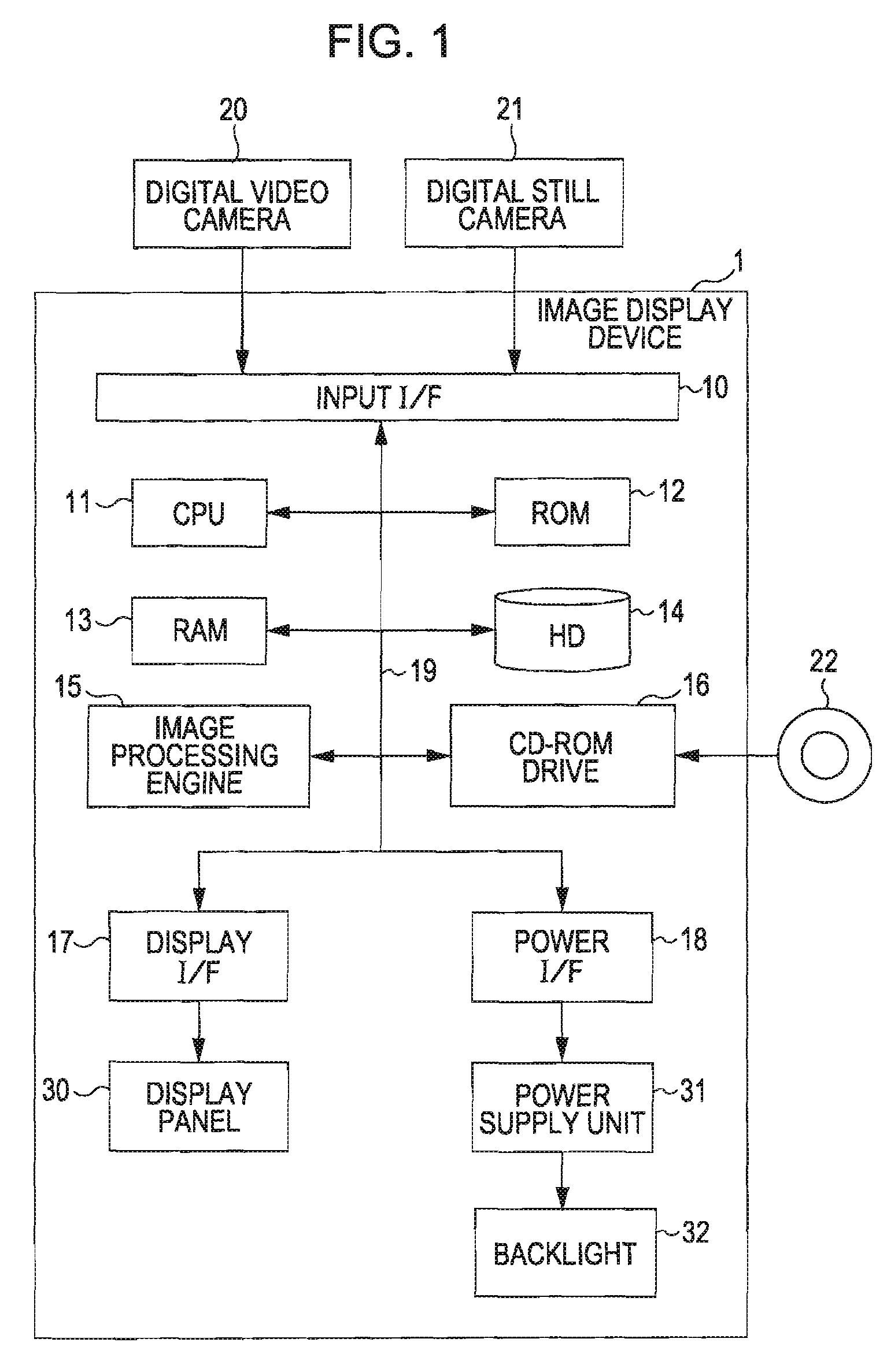
[0039]FIG. 1 is a block diagram that shows the hardware configuration of an image display device according to a first embodiment. As shown in FIG. 1, the image display device 1 includes an input interface (hereinafter referred to as “input I / F”) 10, a CPU 11, a ROM 12, a RAM 13, a hard disk (hereinafter, referred to as “HD”) 14, an image processing engine 15, a CD-ROM drive 16, a display interface (hereinafter, referred to as “display I / F”) 17, and a power I / F 18. These components are connected with each other through a bus 19. In addition, a display panel 30 is connected to the display I / F 17, and a power supply unit 31 is connected to the power I / F 18. Note that a specific example of the image display device 1 may be a laptop computer, a projector, a television, a mobile telephone, and the like, which are able to display an image using the display panel 30. Furthermore, ...

second embodiment

[0087]The following will describe a second embodiment of the invention. The second embodiment differs from the first embodiment in that, in addition to the above described saturation correction, a process to determine the amount of source light in accordance with the luminance and color difference of image data is executed. The reason why the above process is executed will be described below. Owing to the above described brightness correction, the average luminance may be retained in a display image even when dimming is performed. However, there is a possibility that an extreme decrease in saturations occurs in an image having a high saturation colors such as red (R) and blue (B). Red or blue has a high saturation but has a small value in luminance. Therefore, the above steep decrease in saturations is presumably caused by excessive dimming. Specifically, a description will be made with reference to FIG. 10A and FIG. 10B. FIG. 10A and FIG. 10B are views that show the relationship be...


PUM


Abstract

An image display device corrects image data, which are used for displaying an image, using a gray scale value assigned to each pixel and also controls the amount of source light emitted from a light source. The image display device includes a source light amount control device and an image correction device. The source light amount control device determines the amount of source light and then controls the amount of source light. The image correction device corrects a signal used for changing saturations of the image data so as to reduce a change in the saturations due to a change in the amount of source light, the change in the amount of source light being performed by the light source amount control device.

Description

BACKGROUND[0001]1. Technical Field[0002]The present invention relates to an image display device, an image display method, an image display program a recording medium containing the image display program, and an electronic apparatus, which execute a process on input image data.[0003]2. Related Art[0004]In an existing image display device, such as a laptop computer, that uses a non-luminescent display device, such as a liquid crystal panel, when electric power is not supplied from the outside, image display is performed in such a manner that a light source (for example, cold-cathode tube) converts electric power supplied from a battery to light and the amount of light transmitted through the liquid crystal panel is then controlled. In general, of electric power consumed in the whole device, a percentage of electric power consumed by the light source is relatively large. Then, during battery driving, electric power consumed by the device is reduced by reducing (hereinafter, also refer...

Claims


Application Information

Patent Timeline
Patent Type & Authority Applications(United States)
IPC IPC(8): G09G3/36
CPCG09G3/3406G09G5/003G09G5/02G09G2320/0242G09G2360/18G09G2320/066G09G2320/0673G09G2330/021G09G2360/16G09G2320/0626G02F1/133H04N9/64
Inventor MORI, KENJI
Owner SEIKO EPSON CORP
Why Eureka
Try Eureka