
Method and Apparatus for Analyzing Particles in a Fluid

a particle and fluid technology, applied in the field of particle analysis in fluids, can solve the problems of intravenous solution, light obscuration technique, adverse effects on patients,

Active Publication Date: 2008-05-01
PROTEINSIMPLE
View PDF19 Cites 29 Cited by
  • Summary
  • Abstract
  • Description
  • Claims
  • Application Information

AI Technical Summary

Benefits of technology

[0015]wherein said detecting includesadjusting levels of illumination of said sample fluid stream so as to minimize a noise level present on said still images of sample fluid stream;measuring an actual level of illumination used to obtain a particular image of said sample fluid stream, for subsequent processing of such an image;subtracting a background image from said images of the sample fluid stream, and forming background-corrected images, wherein said background image is substantially free of images of particles; andsetting a threshold for the background-corrected images, so as to highlight images of particles present in the background-corrected images of the sample fluid stream.
[0020]a suitably programmed processor for controlling the illumination means and the imaging means, as well as for detecting and counting images of particles in said images of the sample fluid stream, byadjusting levels of illumination of said stream so as to minimize a noise level present on said still images of fluid stream,measuring an actual level of illumination used to obtain a particular image of said fluid stream, for subsequent processing of such an image,subtracting a background image from each of said images of the sample fluid stream, wherein said background image is substantially free of images of particles, andsetting a threshold to thereby background-corrected images, so as to highlight images of particles present in the background-corrected images of sample fluid stream.

Problems solved by technology

The medical reasons for specifying such maximum allowed concentrations is that particulates larger than a certain size, conventionally defined by their equivalent sphere diameter (ESD), can have adverse effects on the patient when injected or placed on the eyes.
The disadvantages of the light obscuration technique stem from the fact that particles in intravenous solutions are composed materials which are highly transparent and often are far from spherical.
As a result, errors in sizing / counting are inevitable.
Another disadvantage of the light obscuration technique is the limited range of particle concentrations that the technique is capable of handling.
In light obscuration, if more than one particle is present in the beam, the signal reductions will be added resulting in errors in size and concentration.
Visual microscopy is a manual operation, and, therefore, is prone to a subjectivity, error, and fatigue of an operator.
Moreover, preparation of samples for microscopic analysis is a lengthy and costly procedure which can only be done by specially trained personnel.

Method used


Image

  • Method and Apparatus for Analyzing Particles in a Fluid
  • Method and Apparatus for Analyzing Particles in a Fluid
  • Method and Apparatus for Analyzing Particles in a Fluid

Examples


Embodiment Construction

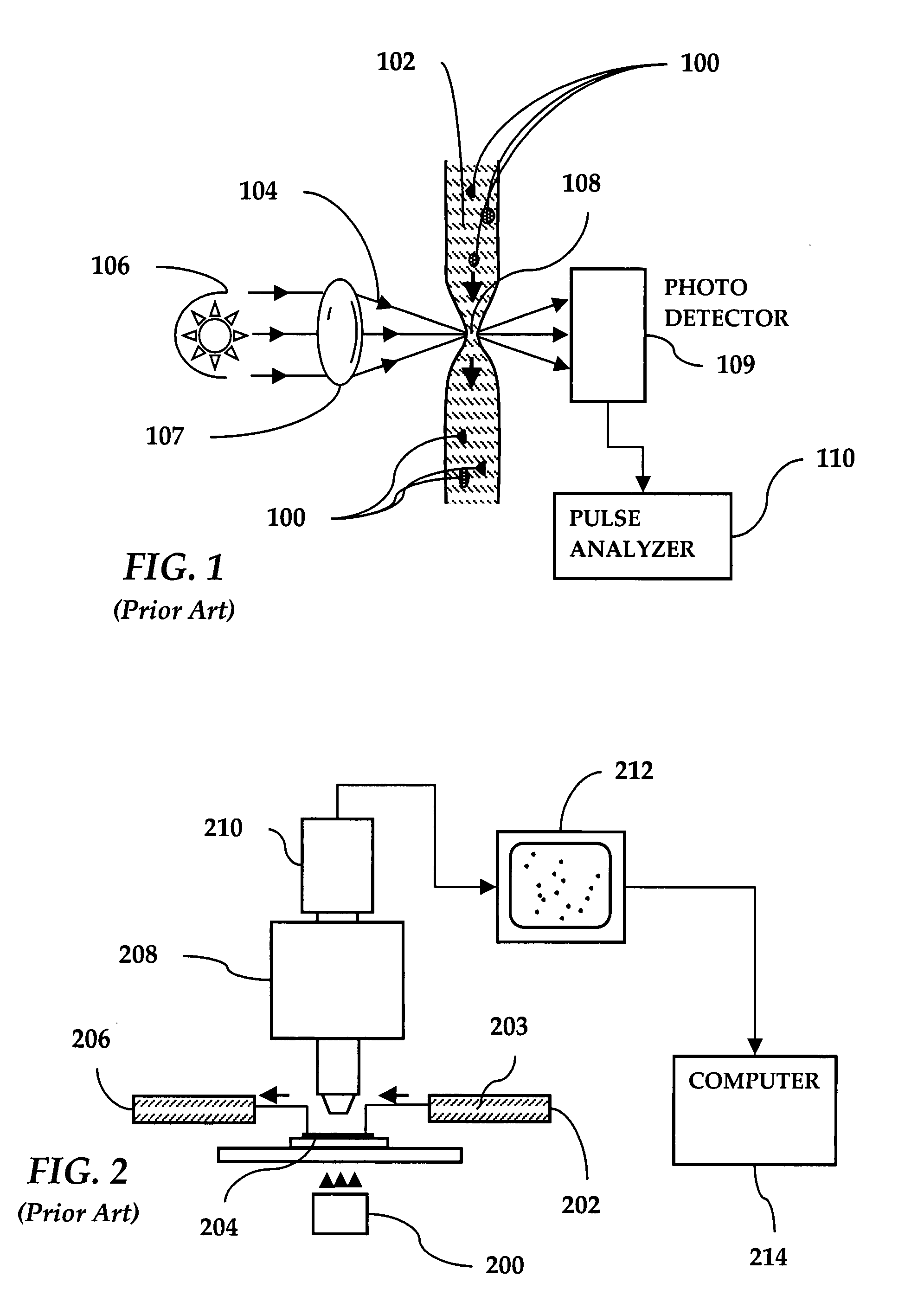
[0032]Referring to FIG. 1, a prior art light obscuration apparatus is shown wherein particles 100 in a fluid 102 are arranged to pass, one by one, through a light beam 104 generated by a light source 106 and focused by a lens 107 onto a measurement area 108. A photodetector 109 is positioned to intercept the light beam 104. A pulse analyzer 110 is coupled to the photodetector 109.

[0033]When a particle 100 in a flowing fluid 102 transits the measurement area 108, the light beam 104 is obscured with a resulting change in signal strength at the photodetector 109. This signal change is picked and measured by the pulse analyzer 110. The signal change is then equated to a particle's equivalent circular diameter (ECD) based on a calibration curve created using polystyrene (PS) spheres of a known size. To the extent that particles in intravenous solutions are composed of different materials and are often far from spherical, errors in sizing and counting are unavoidable. Particles which are ...


PUM

PropertyMeasurementUnit
widthaaaaaaaaaa
widthaaaaaaaaaa
widthaaaaaaaaaa

Abstract

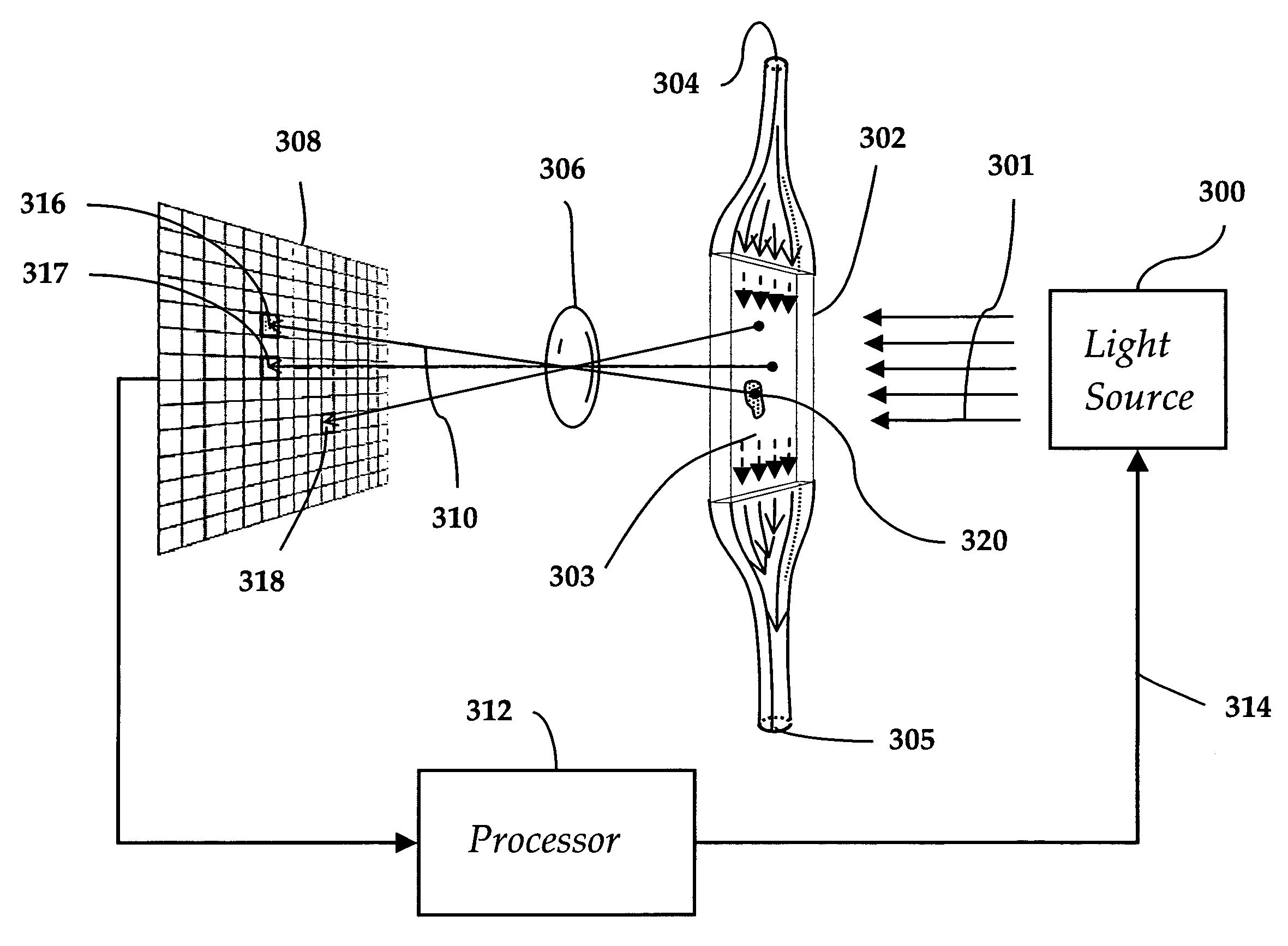
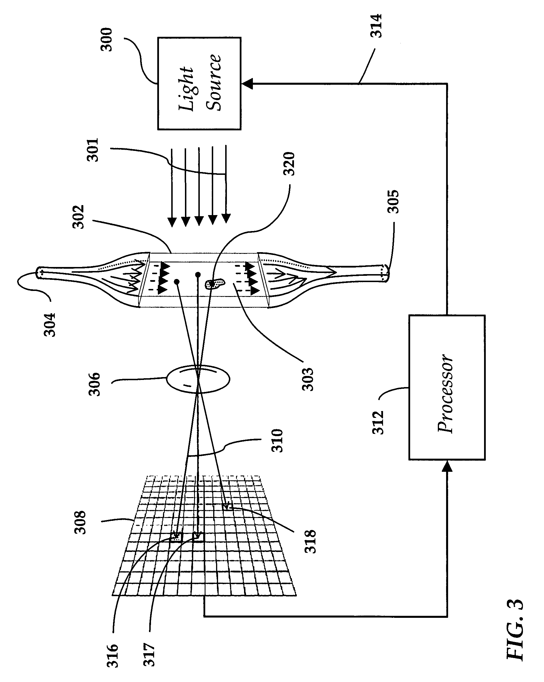
A method and apparatus for analyzing particles in a fluid, such as proteinaceous particles in a pharmaceutical formulation intended for parenteral delivery, are disclosed. The method comprises arranging a fluid to form a wide and shallow stream, acquiring a sequence of magnified still images of the stream, and processing said images, so as to highlight images of particles in the flowing fluid. The apparatus includes a light source, a flow cell, a lens with increased depth of view, a detector array, and a processor for acquiring and processing the images of particles in the fluid stream.

Description

CROSS-REFERENCE TO RELATED APPLICATIONS[0001]The present invention claims priority from U.S. provisional patent application No. 60 / 855,116 filed Oct. 30, 2006, which is incorporated herein by reference.TECHNICAL FIELD[0002]The present invention is related to particle analysis in fluids, or more precisely, to optical analysis of particle populations in pharmaceutical formulations such as proteinaceous pharmaceutical solutions intended for parenteral delivery.BACKGROUND OF THE INVENTION[0003]A requirement to detect, size and count individual particles within a particle population suspended in a transparent fluid is frequently encountered in parenteral and general pharmaceutical analysis. Typical populations of interest include aggregates, contaminants, bubbles, and other particles.[0004]Regulatory bodies such as the US FDA apply standards for parenteral injectable and ophthalmic solutions which specify the maximum concentration of particles larger than certain sizes which the solution...

Claims


Application Information

Patent Timeline
Patent Type & Authority Applications(United States)
IPC IPC(8): G01N21/00
CPCG01N15/1463G01N15/1433
Inventor OMA, PETERDIGGINS, JARRET A.MATIAS, ANTONIO J.G.
Owner PROTEINSIMPLE
Learn More