
Optical architecture requiring a single tilt mirror to pass a collimated beam through an aperture stop, centered, at a desired angle, in one or two dimensions

a technology of optical architecture and collimation beam, which is applied in the direction of mirrors, instruments, mountings, etc., can solve the problems of preventing optical architecture, not operating properly, and large vacuum chambers for this application, and achieves the effects of reducing the cost of operation, and reducing the number of optical structures

Inactive Publication Date: 2008-05-01
NORTHROP GRUMMAN SYST CORP
View PDF1 Cites 1 Cited by
  • Summary
  • Abstract
  • Description
  • Claims
  • Application Information

AI Technical Summary

Benefits of technology

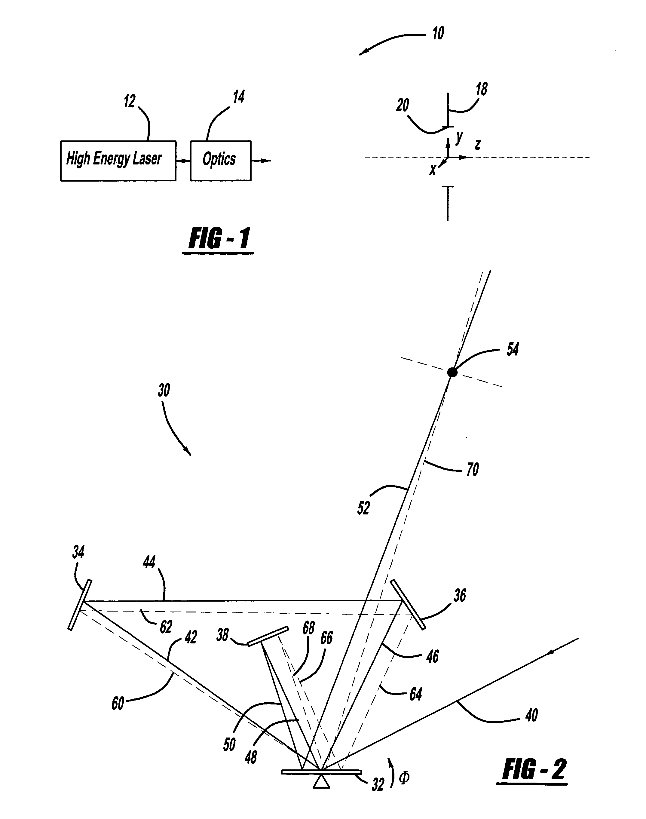
[0007]In accordance with the teachings of the present invention, an optical architecture is disclosed for a high-energy laser system that directs a collimated laser beam through an aperture stop at a desired angle. In one embodiment, the optical architecture includes a single tilt mirror and three stationary mirrors that direct the laser beam in one dimension. The laser beam is reflected off of the mirrors in the same plane and is reflected off of the tilt mirror three times. The first two reflections off of the tilt mirror translate the beam and the third reflection causes the beam to be directed at the desired angle. In another embodiment, the optical architecture includes a single tip-tilt mirror and eight stationary mirrors that direct the beam in two dimensions. The laser beam is reflected off of the mirrors in two planes and is reflected off of the tip-tilt mirror three times. The first two reflections off of the tip-tilt mirror translate the beam and the third reflection causes the beam to be directed at the desired angle.

Problems solved by technology

Because the beam is high energy, it is typically undesirable to re-image the beam, i.e., bring it to a focus, within the optical architecture 14 because the focused beam causes air to break down, and other adverse effects, which prevents the optical architecture 14 from operating properly in a manner that is well understood in the art.
However, such vacuum chambers for this application are typically large, heavy, complex and costly.
However, the algorithms required to tilt two mirrors accurately and properly in concert with each other are difficult to implement and are typically unreliable.

Method used


Image

  • Optical architecture requiring a single tilt mirror to pass a collimated beam through an aperture stop, centered, at a desired angle, in one or two dimensions
  • Optical architecture requiring a single tilt mirror to pass a collimated beam through an aperture stop, centered, at a desired angle, in one or two dimensions
  • Optical architecture requiring a single tilt mirror to pass a collimated beam through an aperture stop, centered, at a desired angle, in one or two dimensions

Examples


Embodiment Construction

[0017]The following discussion of the embodiments of the invention directed to an optical architecture for directing a collimated optical beam through an aperture stop at a desired angle is merely exemplary in nature, and is in no way intended to limit the invention or its applications or uses. For example, the optical architecture of the invention has particular application for directing a high-energy laser beam. However, as will be appreciated by those skilled in the art, the optical architecture of the invention may have other applications for other optical systems.

[0018]The present invention proposes an optical architecture suitable for the optical architecture 14 that employs a single tilt mirror, and can direct a collimated laser beam in one or two dimensions. As will be discussed in detail below, the optical architecture of the invention maintains the laser beam collimation and directs the beam through the aperture 20 with a desired beam angle.

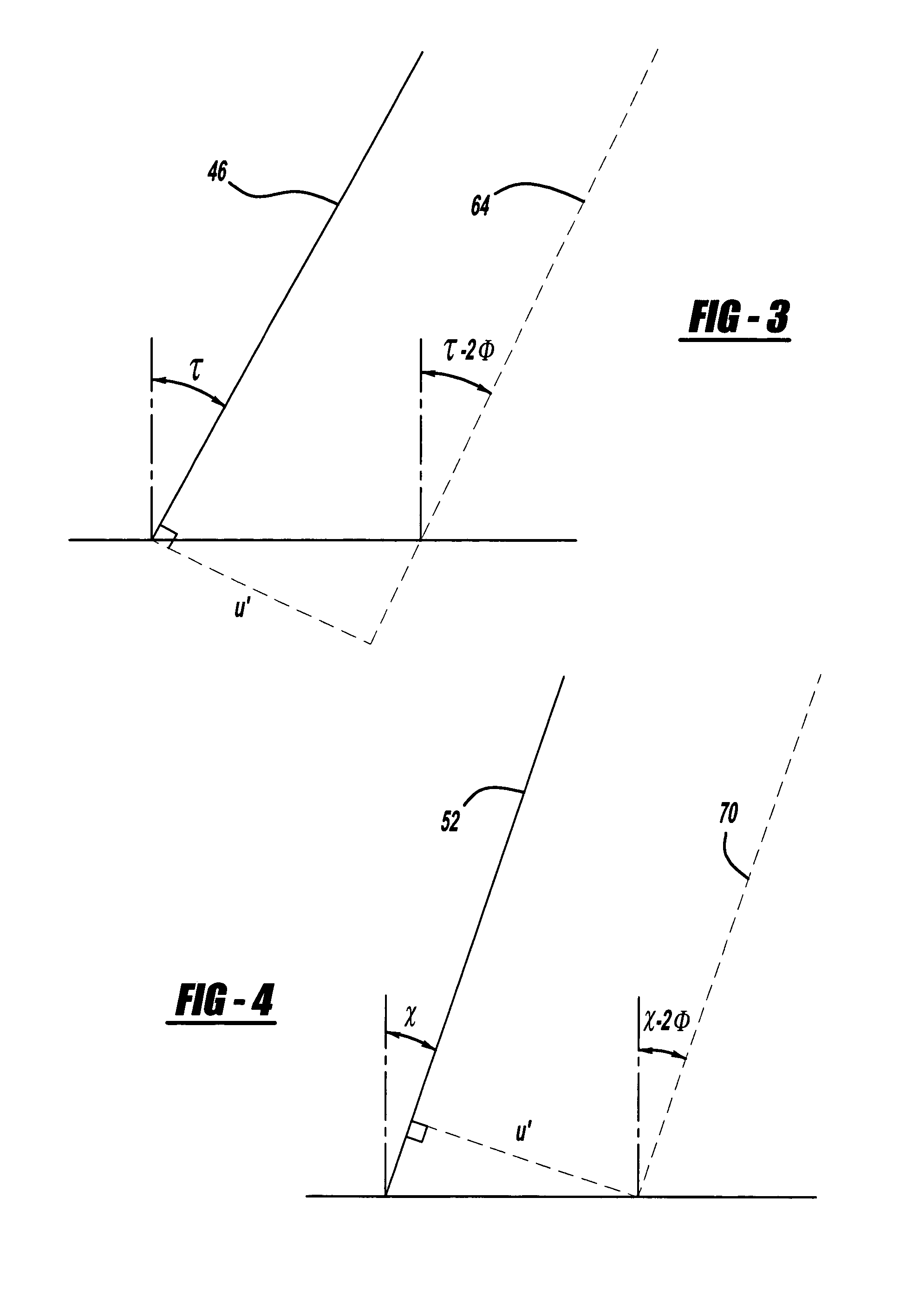
[0019]FIG. 2 is a plan view of a...


PUM


Abstract

An optical architecture for a high-energy laser that directs a collimated laser beam through an aperture stop at a desired angle. In one embodiment, the optical architecture includes a single tilt mirror and three stationary mirrors that direct the laser beam in one dimension. The laser beam is reflected off of the mirrors in the same plane and is reflected off of the tilt mirror three times. The first two reflections off of the tilt mirror translate the beam and the third reflection causes the beam to be directed at the desired angle. In another embodiment, the optical architecture includes a single tip-tilt mirror and eight stationary mirrors that direct the beam in two dimensions. The laser beam is reflected off of the mirrors in two planes and is reflected off of the tip-tilt mirror three times. The first two reflections off of the tip-tilt mirror translate the beam and the third reflection causes the beam to be directed at the desired angle.

Description

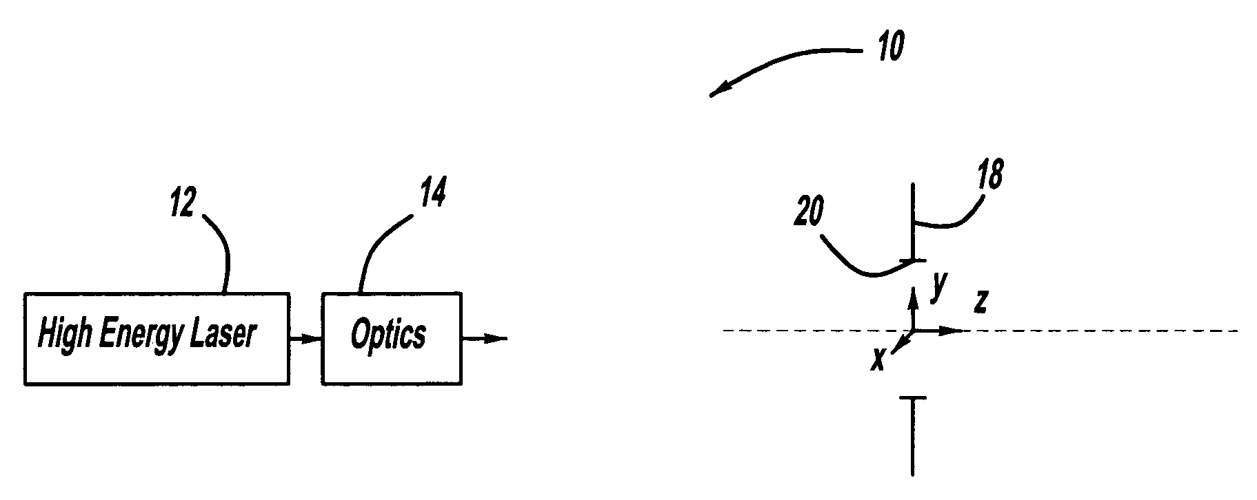
BACKGROUND OF THE INVENTION[0001]1. Field of the Invention[0002]This invention relates generally to an optical architecture for directing a laser beam and, more particularly, to an optical architecture for directing a collimated high-energy laser beam through an aperture stop at a desired angle in one or two dimensions using a single tilt mirror.[0003]2. Discussion of the Related Art[0004]High-energy lasers (HEL) have various applications in the art, such as target range finding and destruction. FIG. 1 is a general plan view of a laser system 10 including a high-energy laser 12 that emits a collimated laser beam. The laser beam is received by an optical architecture 14 that provides beam conditioning and directivity to cause the beam to be emitted through an aperture stop 18 having an aperture 20 at a desired angle towards a target (not shown). Because the beam is high energy, it is typically undesirable to re-image the beam, i.e., bring it to a focus, within the optical architectur...

Claims


Application Information

Patent Timeline
Patent Type & Authority Applications(United States)
IPC IPC(8): G02B5/08
CPCG02B26/101
Inventor FARRELL, THOMAS C.
Owner NORTHROP GRUMMAN SYST CORP
Learn More