
Apparatus, system, and method for redundant identification of a storage medium format

a technology of storage medium and storage medium, applied in the field of storage systems, can solve the problems of inability to read the cm, corrupted data in the cm, and inability to provide the cm, so as to reduce the read and write time to the storage medium and reduce the wear and tear of mechanical components

Inactive Publication Date: 2008-05-01
IBM CORP
View PDF9 Cites 1 Cited by
  • Summary
  • Abstract
  • Description
  • Claims
  • Application Information

AI Technical Summary

Benefits of technology

[0013]From the foregoing discussion, it should be apparent that a need exists for an apparatus, system, and method that redundantly identify a storage medium format. Beneficially, such an apparatus, system, and method would reduce read and write time to the storage medium, and reduce wear and tear on mechanical components of some storage media.

Problems solved by technology

However, in certain situations the CM may not be available.
For example, the data in the CM may be corrupted, the drive may be unable to read the CM, or the like.
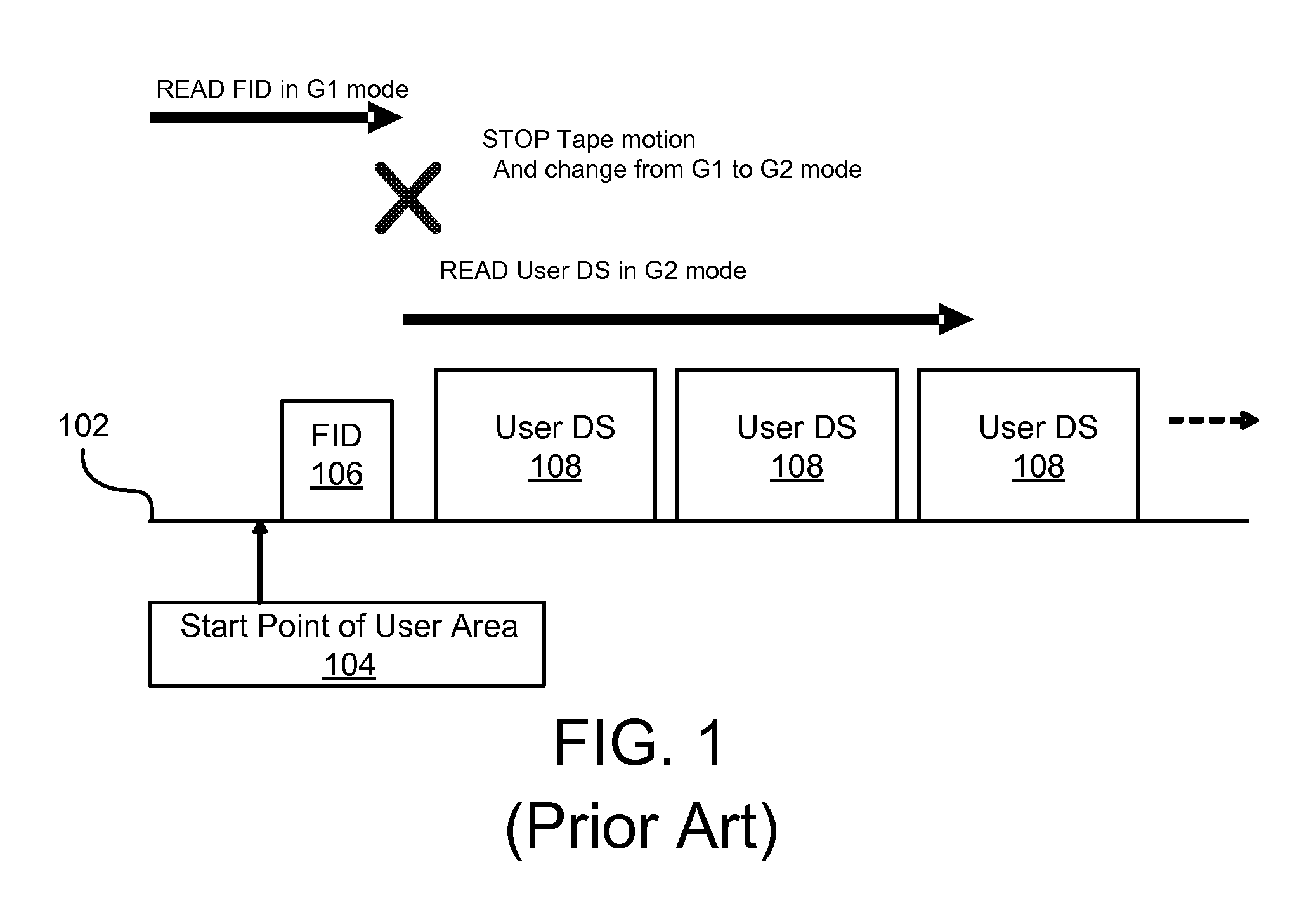
If the FID is unavailable, the drive is unable to determine the layout information required to read and write the tape.
If this information is unavailable, the tape drive is unable to read or write data to the tape cartridge.
However, certain problems may arise when tapes 102 configured for different generations of storage equipment are employed.
For example, an error may occur if a G2 tape is loaded into a G1 tape drive.
Although the tape 102 may be physically compatible with the drive, the formats may be incompatible.
This problem is exacerbated with certain operations.
These operations typically waste read and write time.
Additionally, in systems where mechanical components are required to change in order to change configurations, excessive wear and tear may occur.

Method used


Image

  • Apparatus, system, and method for redundant identification of a storage medium format
  • Apparatus, system, and method for redundant identification of a storage medium format
  • Apparatus, system, and method for redundant identification of a storage medium format

Examples


Embodiment Construction

[0033]Many of the functional units described in this specification have been labeled as modules, in order to more particularly emphasize their implementation independence. For example, a module may be implemented as a hardware circuit comprising custom VLSI circuits or gate arrays, off-the-shelf semiconductors such as logic chips, transistors, or other discrete components. A module may also be implemented in programmable hardware devices such as field programmable gate arrays, programmable array logic, programmable logic devices or the like.

[0034]Modules may also be implemented in software for execution by various types of processors. An identified module of executable code may, for instance, comprise one or more physical or logical blocks of computer instructions which may, for instance, be organized as an object, procedure, or function. Nevertheless, the executables of an identified module need not be physically located together, but may comprise disparate instructions stored in d...


PUM

PropertyMeasurementUnit
volumeaaaaaaaaaa
lengthaaaaaaaaaa
storage densitiesaaaaaaaaaa

Abstract

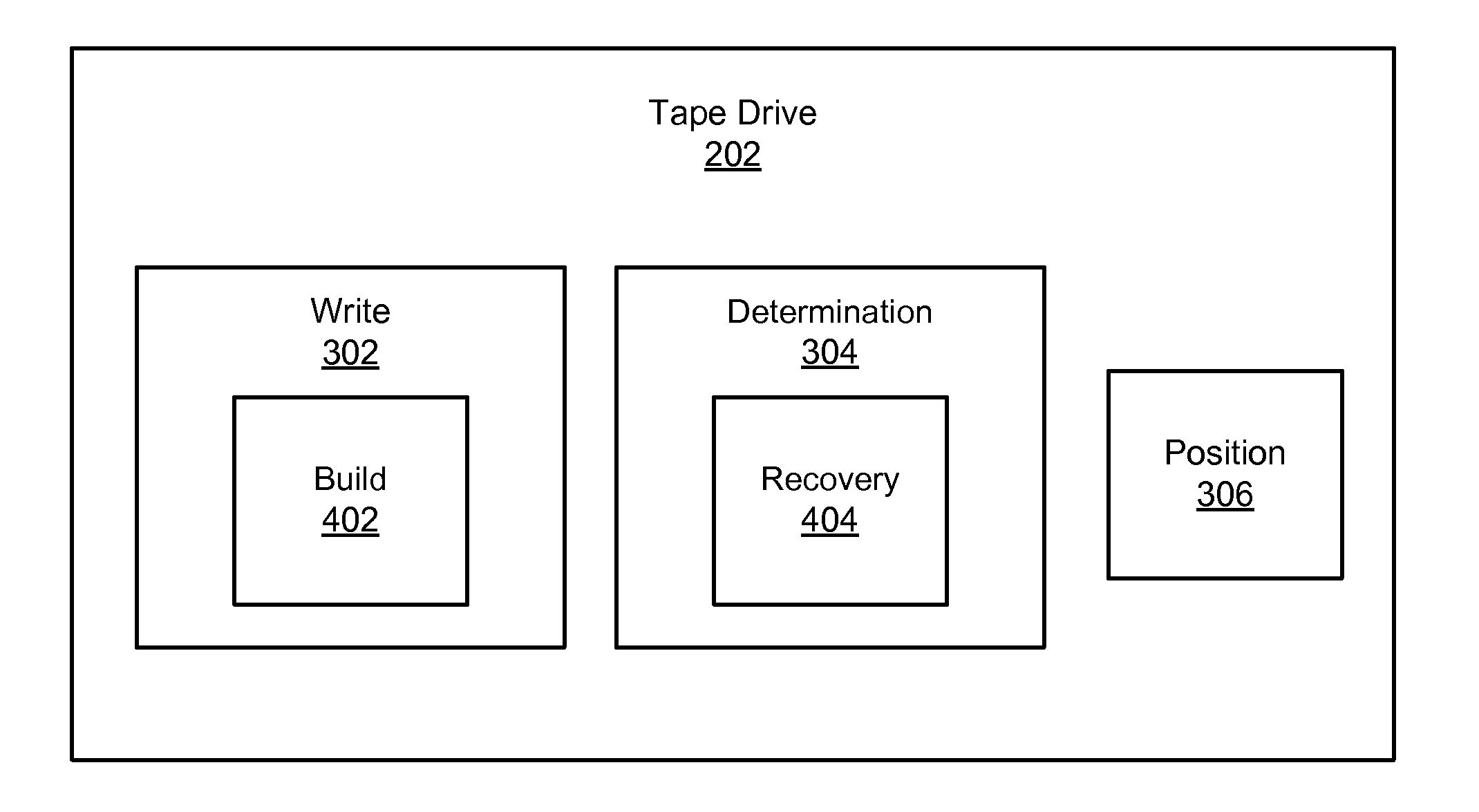
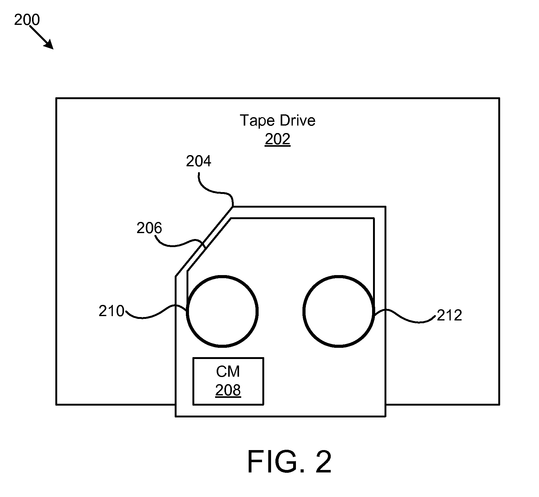
An apparatus, system, and method are disclosed for redundant identification of a storage medium format. The apparatus for redundant identification of a storage medium format is provided with a plurality of modules configured to functionally execute the necessary steps of writing a Format Identification Data Set (“FID”) to a plurality of predetermined locations on the storage medium, determining a format of the storage medium based on information in the FID, and setting a starting position on the storage medium for a subsequent operation, wherein the starting position is associated with the format of the storage medium. These modules in the described embodiments include a write module, a determination module, and a position module. In a further embodiment, the storage medium may include a data storage tape housed within a tape cartridge, wherein the tape cartridge further comprises a cartridge memory (“CM”) for storing a CM FID.

Description

BACKGROUND OF THE INVENTION[0001]1. Field of the Invention[0002]This invention relates to storage systems and more particularly relates to redundant identification of a storage medium format.[0003]2. Description of the Related Art[0004]Common storage media and storage systems include various hardware and media configurations and formats. As technology progresses, storage densities improve, error rates are reduced, and data reliability is increased. These advances are typically implemented in successive versions, revisions, or generations of storage systems or storage media products.[0005]For example, the 3592 Enterprise™ tape storage system offered by International Business Machines® (“IBM”) is just one of many members of a family of storage system products. Changes may be implemented in various revisions and generations even among individual models. For example, the model 3592 Enterprise™ tape storage system includes a First Generation (“G1”), and a Second Generation (“G2”). In thi...

Claims


Application Information

Patent Timeline
Patent Type & Authority Applications(United States)
IPC IPC(8): G11B5/02
CPCG11B27/11G11B2220/90G11B2220/655G11B27/322
Inventor GRECO, PAUL MERRILLITAGAKI, HIROSHIKATAGIRI, TAKASHINAKAYAMA, HIROKAZU
Owner IBM CORP
Learn More