Boil Cooling Method, Boil Cooling Apparatus, Flow Channel Structure, and Applied Technology Field Thereof

a technology of flow channel structure and boil cooling method, which is applied in the field of boil cooling method, boil cooling apparatus, flow channel structure, and applied technology, and can solve the problems of large growth rate of heat flux, increase of heat flux rate, and increase of quantity of bubbles generated at the surface of heating blocks

Inactive Publication Date: 2008-05-08
TOKYO UNIVERSITY OF SCIENCE
View PDF6 Cites 13 Cited by
  • Summary
  • Abstract
  • Description
  • Claims
  • Application Information

AI Technical Summary

Benefits of technology

[0115]As described above, according to the present invention, a boil cooling method, a boil cooling apparatus, and a flow channel structure, that have been heretofore unavailable, can be provided. A minute bubble by boil cooling is generated in the vicinity of a cooling surface, however, according to the present invention, because the cooling liquid flowing through the sub-flow channel is supplied through a nozzle from “the opening part in the vicinity of the cooling surface”, the minute bubble generated in the vicinity of the cooling surface is efficiently miniaturized or collapsed and “shifting of the boiling form” to the transition boiling area can be effectively suppressed, so that realizing satisfactory boil cooling by nucleate boiling can be enabled even in “a high temperature area in which transition boiling might occur if it is in a conventional boil cooling method”.

Problems solved by technology

As a minute bubble starts to be generated at the surface of the heating block, “the growth rate of heat flux” increases, and if heating the heating block is further continued, the quantity of bubbles generated at the surface of the heating block also increases, and the heat flux also continues to increase at a large growth rate, which however is finally saturated.
If the heating block is heated even after the heat flux has reached the critical heat flux, at the part of the surface of the heating block the large bubble has adhered to, the heating surface starts to be dried, and with a rapid rise of the heating surface temperature, the heat flux rapidly decreases, so that the cooling effect rapidly deteriorates.
At this dried part, the heat energy of the heating block is transferred as radiant heat to the liquid, and the heat flux shifts to increase again, however, because the heating surface is not in contact with the liquid, the temperature of the heating block also increases, and if this temperature exceeds a melting point of the heating block, the heating surface “burns out”.
Generally, after the state in which the heat flux is the critical heat flux, “the process leading to burning out from the transition boiling through the film boiling” develops extremely rapidly, and control thereof is extremely difficult, so that boil cooling has been heretofore commonly performed in “the area of nucleate boiling in which the heat flux is equal to or below the critical heat flux”.
However, even when performing boil cooling using sub-cooled cooling liquid, with passing of the time that the cooling liquid flows along the cooling surface, the temperature of the whole part of the cooling liquid gradually increases, and the effect of sub-cooling inevitably decreases, so that there is a limit to “performing boil cooling to a large cooling area without causing transition boiling” in a considerably high temperature area.
Further, it is expected in future that a cooling method enabling obtaining the heat flux of about 300 W / cm2 or more will be required, however, those requirements cannot be met by the conventional cooling method, and the advent of a boil cooling method capable of dealing with those requirements is desired.

Method used


Image

  • Boil Cooling Method, Boil Cooling Apparatus, Flow Channel Structure, and Applied Technology Field Thereof
  • Boil Cooling Method, Boil Cooling Apparatus, Flow Channel Structure, and Applied Technology Field Thereof
  • Boil Cooling Method, Boil Cooling Apparatus, Flow Channel Structure, and Applied Technology Field Thereof

Examples


example 1

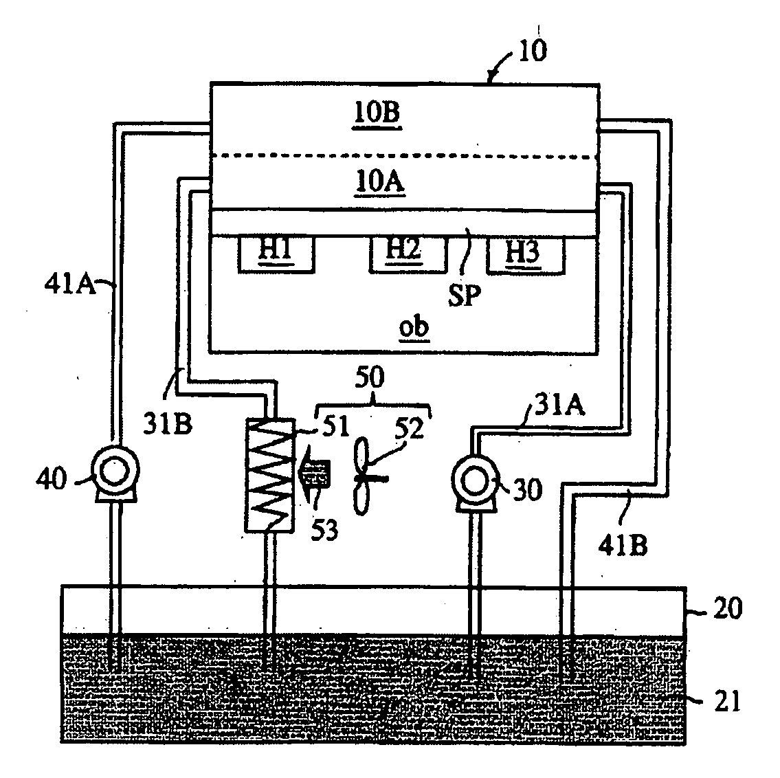
[0192]The construction of an exemplary apparatus is substantially the same as that of the embodiment described according to FIG. 1. It has been assumed that an inverter, which is a semiconductor device, is used as the object to be cooled, and as the heat spreader of the inverter, the one 100 mm in width and 150 mm in length has been assumed.

[0193]The case has been assumed that the flow channel structure part as described according to FIG. 1 is constructed on the heat spreader, with the surface of the heat spreader made to serve as the cooling surface, by aluminum with the lengthwise direction of the heat spreader made to serve as the flow channel direction, the flow channel structure part is integrated with the inverter to be constructed as “the flow channel structure”, and both of the main flow channel and the sub-flow channel are respectively divided by partition walls in “an aligned grid form” in the direction perpendicular to the direction of flow of the cooling liquid and paral...

example 2

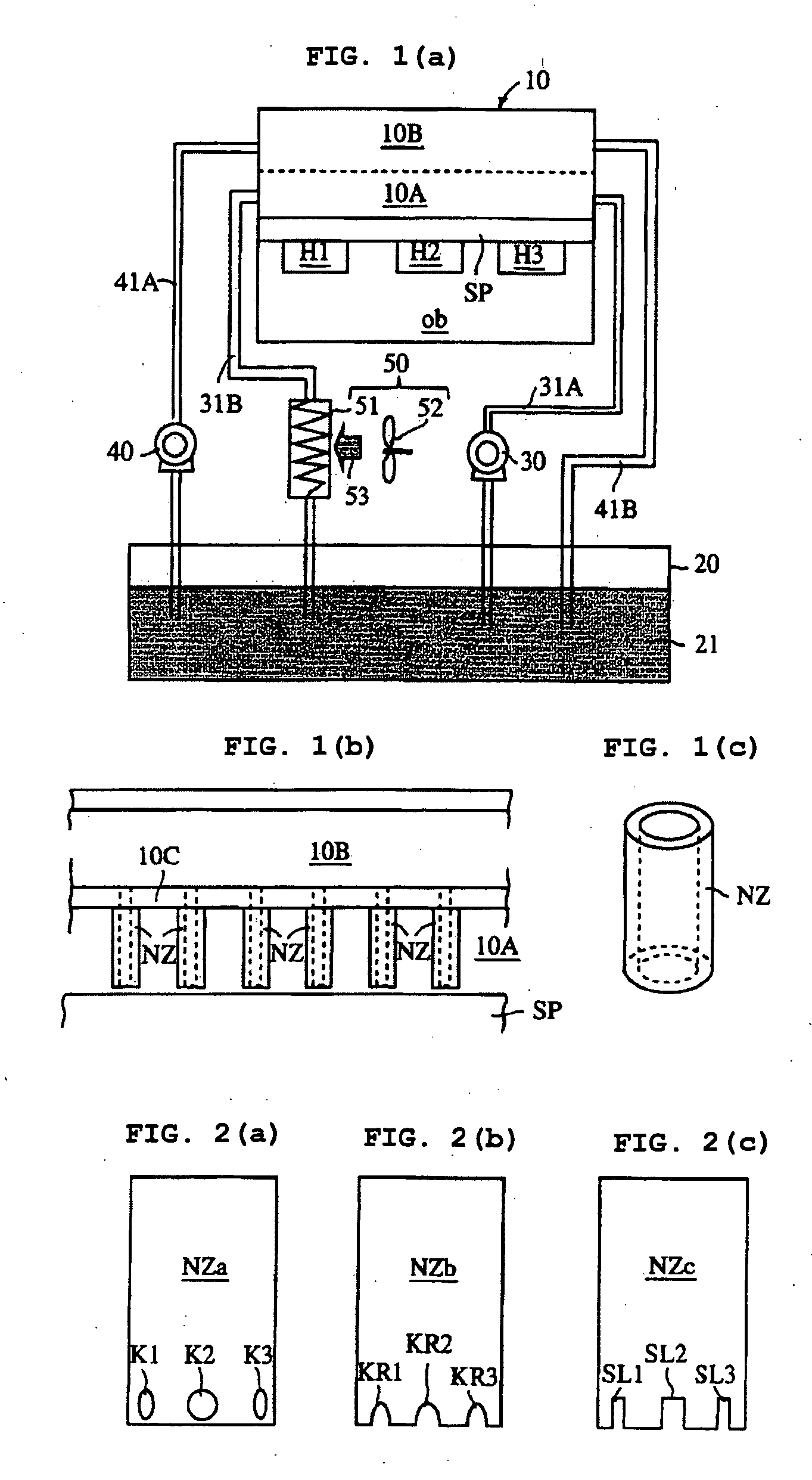
[0198]The passive cooling method and the active cooing method have been performed using the flow channel structure, which is substantially the same as the one described in Example 1 in construction except that notched type nozzles of FIG. 2(c) have been used and that stainless steel has been used as the material for the flow channel structure.

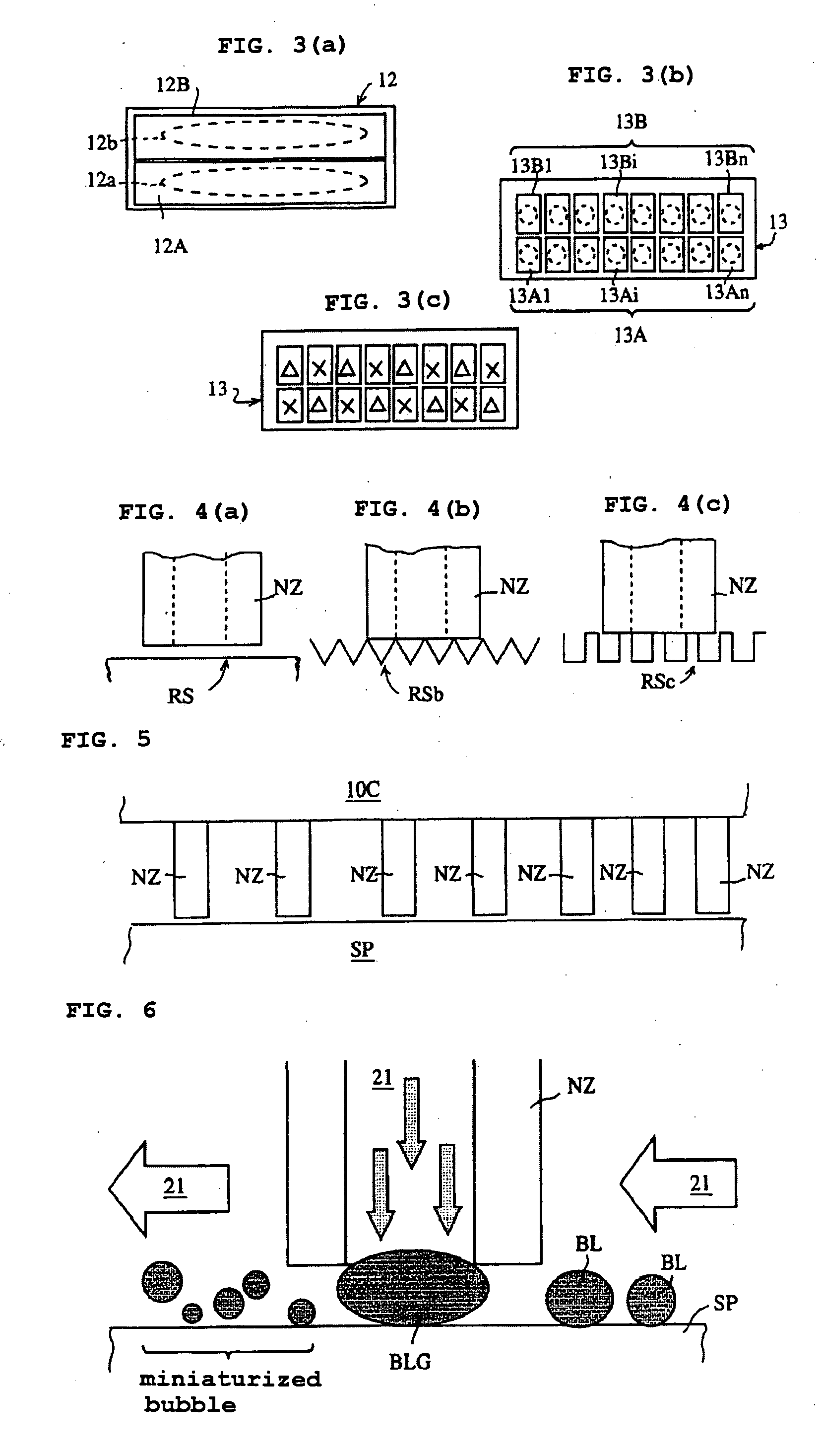
[0199]When “the passive cooling method” has been performed using distilled water as the cooling liquid and supplying the cooling liquid, under the condition that the liquid sub-cooling degree is 40K and the flow velocity to the main flow channel is 0.05 m / sec, from needle nozzles toward the cooling surface in the state that the cooling liquid exudes from the needle nozzles, the heat-removing heat flux of 60 W / cm2 has been obtained.

[0200]Thereafter, the temperature of the cooling surface and the heat flux have been detected with a temperature sensor installed at the cooling surface, and as the amount of heat generation of the cooling surface inc...


PUM


Abstract

In the process of boil cooling, boil cooling by nucleate boiling in a temperature area wherein transition boiling may occur is enabled to a larger cooling area.
A boil cooling method of the present invention forms, with a surface of an object to be cooled ob or a surface of a heating member in close contact with the surface of the object to be cooled made to serve as a cooling surface, a main flow channel 10A and a sub-flow channel 10B for a cooling liquid from the side of the cooling surface in the above-described order, arranges a plurality of nozzles NZ penetrating a partition wall 10C separating the sub-flow channel 10B and the main flow channel 10A and protruding into the main flow channel 10A in a flow channel direction of the main flow channel, causes tip end parts of individual nozzles NZ to be in the vicinity of or in contact with the cooling surface, causes a cooling liquid 21 to circulate to the main flow channel 10A and the sub-flow channel 10B, and cools the cooling surface by boiling of the cooling liquid flowing through the main flow channel 10A, and at the same time, supplies the cooling liquid at the side of the sub-flow channel 10B from the side of the sub-flow channel 10B through each of the nozzles NZ to the vicinity of the cooling surface, and cools the cooling liquid in the main flow channel.

Description

TECHNICAL FIELD[0001]The present invention relates to a boil cooling method, a boil cooling apparatus carrying out the boil cooling method, a flow channel structure for use in the boil cooling apparatus, and an application product to which the method, the apparatus or the structure has been applied.BACKGROUND ART[0002]When heating of liquid is continued, the liquid temperature gradually rises and reaches “a saturation temperature” wherein the liquid temperature does not rise any more. If the liquid is further heated, “vaporization of liquid” occurs in the liquid. This state is boiling, and the above-described saturation temperature is called a boiling point.[0003]In the boiling state, the liquid temperature does not rise, and the energy to be added to liquid by heating is consumed in “vaporizing the liquid inside of the liquid”. This heat energy is called “latent heat”. The latent heat is extremely large as compared with the heat energy raising the temperature of liquid. Accordingly...

Claims


Application Information

Patent Timeline
Patent Type & Authority Applications(United States)
IPC IPC(8): H01L23/427F25D9/00F28D15/02
CPCF24F5/0035F25B2339/021F25D7/00F28F13/02H01L23/427Y10S165/908Y02B30/545H01L2924/0002H01L2924/00Y02B30/54
Inventor SUZUKI, KOICHIKAWAMURA, HIROSHIOHTA, HARUHIKOABE, YOSHIYUKI
Owner TOKYO UNIVERSITY OF SCIENCE
Why Eureka
Try Eureka