
Paintball firing mechanism

Inactive Publication Date: 2008-05-08
COLE CHRISTOPHER
View PDF10 Cites 37 Cited by
  • Summary
  • Abstract
  • Description
  • Claims
  • Application Information

AI Technical Summary

Benefits of technology

[0011]It is, therefore, a primary object of the present invention to provide a high-efficiency paintball marker incorporating a pneumatic firing mechanism with selectable single / burst firing modes that makes more efficient use of compressed gas, thereby allowing firing of more rounds per charge.
[0012]It is another object to provide a pneumatic firing mechanism for a paintball marker having selectable burst-firing modes and integrated bolt and ram to improve efficiency and yet simplify manufacturing.
[0013]In accordance with the foregoing objects, the present invention provides a paintball marker incorporating a pneumatic firing mechanism with selectable single / burst firing modes, that makes more efficient use of compressed gas, thereby allowing firing of more rounds per charge. The marker incorporates an electronic trigger (E-trigger) that actuates an improved pneumatic firing mechanism with selectable single / burst firing modes. The electronic trigger comprises a programmable processor-based controller board that can be programmed by insertion of pre-programmed EPROM chips to achieve semi-automatic modes, burst modes (firing one, two, three or more times with a single pull of the trigger), or fully automatic (continuous firing) modes. The various modes are determined by a software program on the EPROM, and the EPROM can be swapped out for addition of new or different modes. The particular mode is set by the user. The pneumatic firing mechanism comprises an integrated bolt and ram that simplifies manufacturing and makes more efficient use of compressed gas, thereby allowing firing of more rounds per charge. Low pressure is employed in the gun in order to move the bolt rapidly forwardly towards its front shooting position, where the bolt causes high pressure gas to be released into the barrel through a high pressure gas passageway running through the center of the bolt. The improved bolt includes an annular sleeve that slides within the chamber of the gun, and a ram slidably inserted into the sleeve. The ram is defined by a single central passage. The ram has only a central through-bore (not flared ports) and is much simpler to manufacture.
[0014]The net result is a high-efficiency tournament grade paintball marker that makes more efficient use of compressed gas, thereby allowing firing of more rounds per charge, and which is nevertheless simple in construction and easier to manufacture.

Problems solved by technology

Efficiency is important since the capacity of the gas cartridges is limited.
This abrupt right-angle junction creates turbulence in the flow stream and deprives it of efficiency.

Method used


Image

  • Paintball firing mechanism
  • Paintball firing mechanism
  • Paintball firing mechanism

Examples


Embodiment Construction

)

[0022]The present invention is a paintball marker incorporating a pneumatic firing mechanism with selectable single / burst firing modes, and an integrated bolt and ram that simplifies manufacturing and makes more efficient use of compressed gas, thereby allowing firing of more rounds per charge.

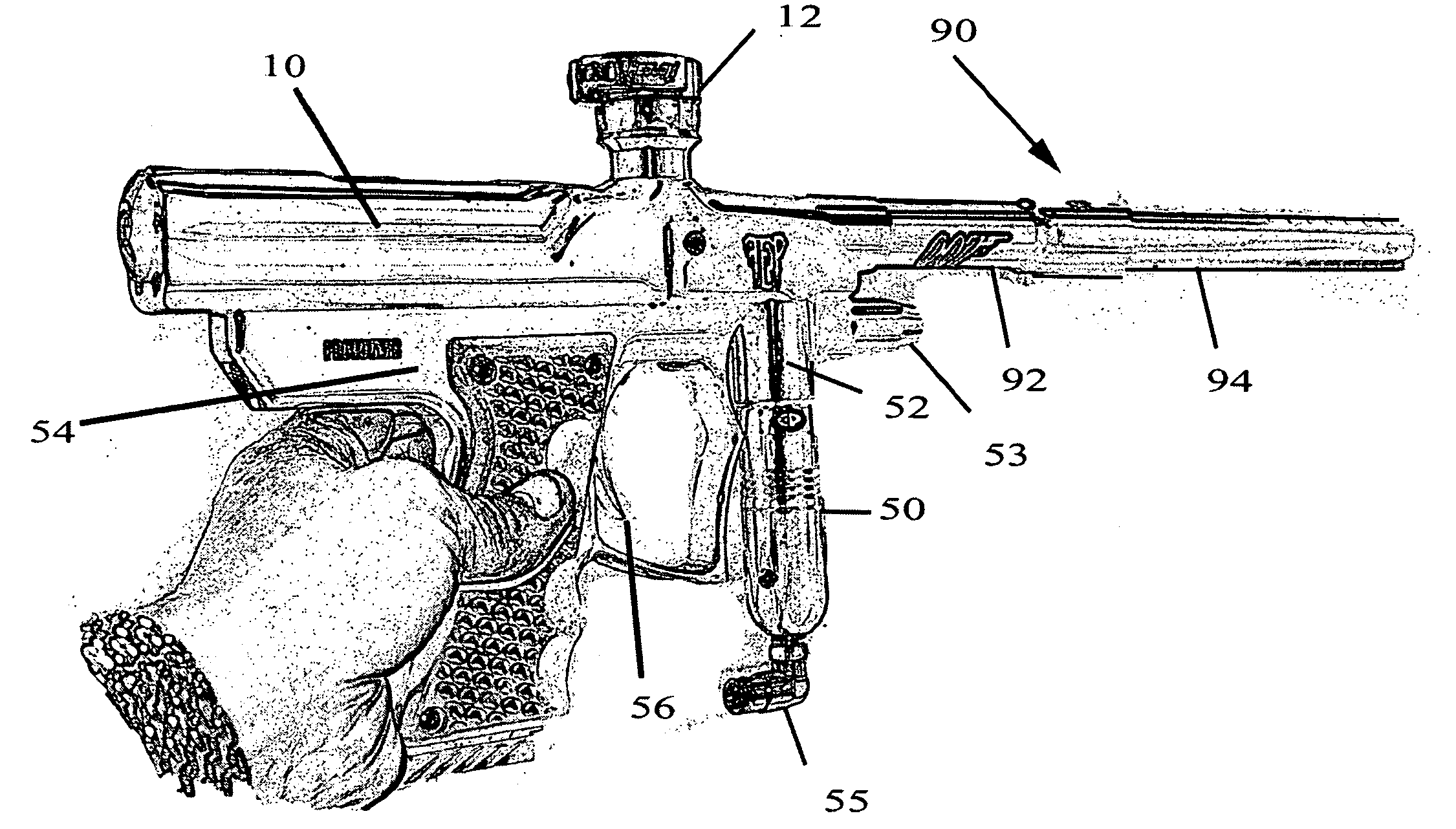
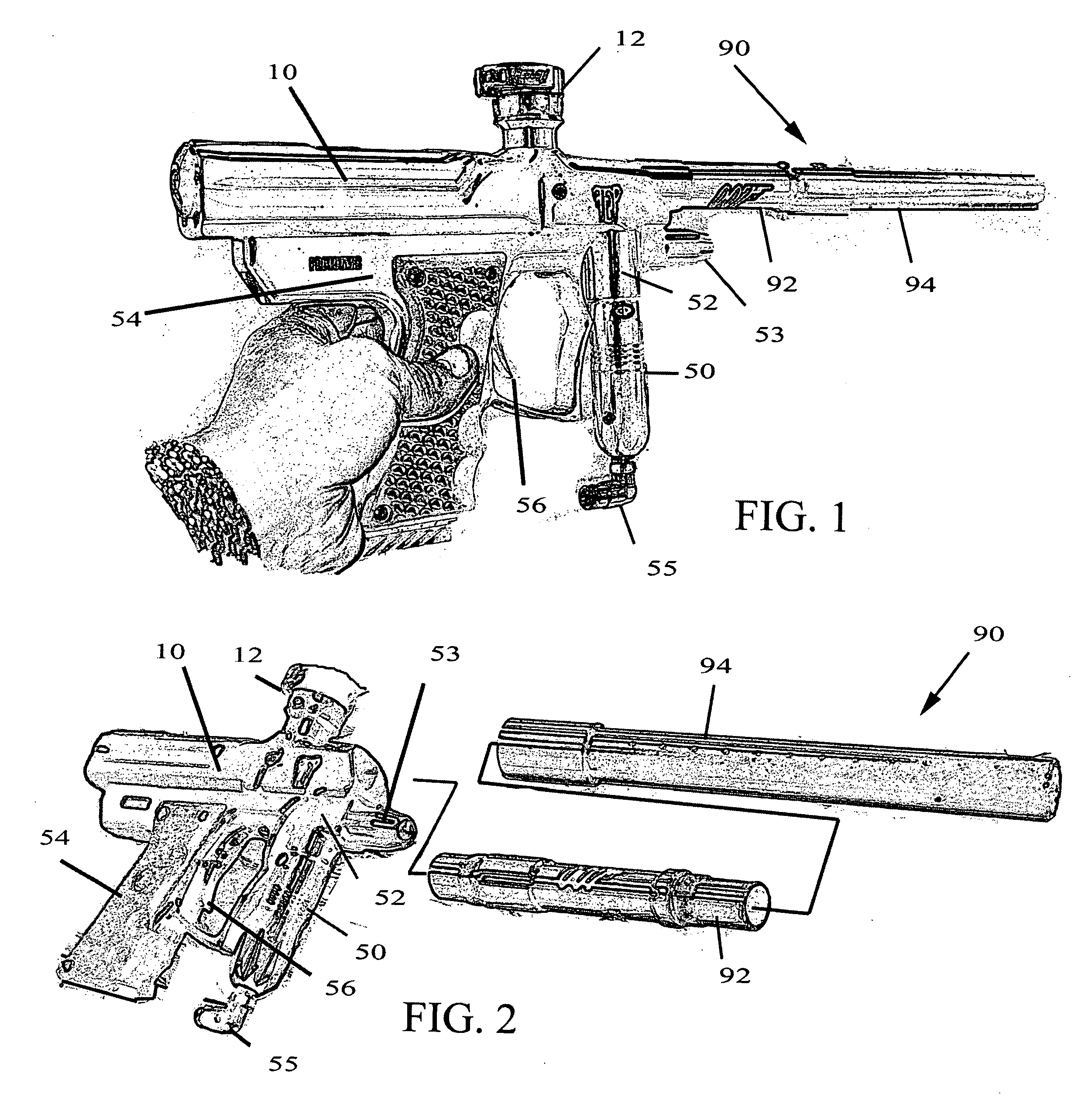
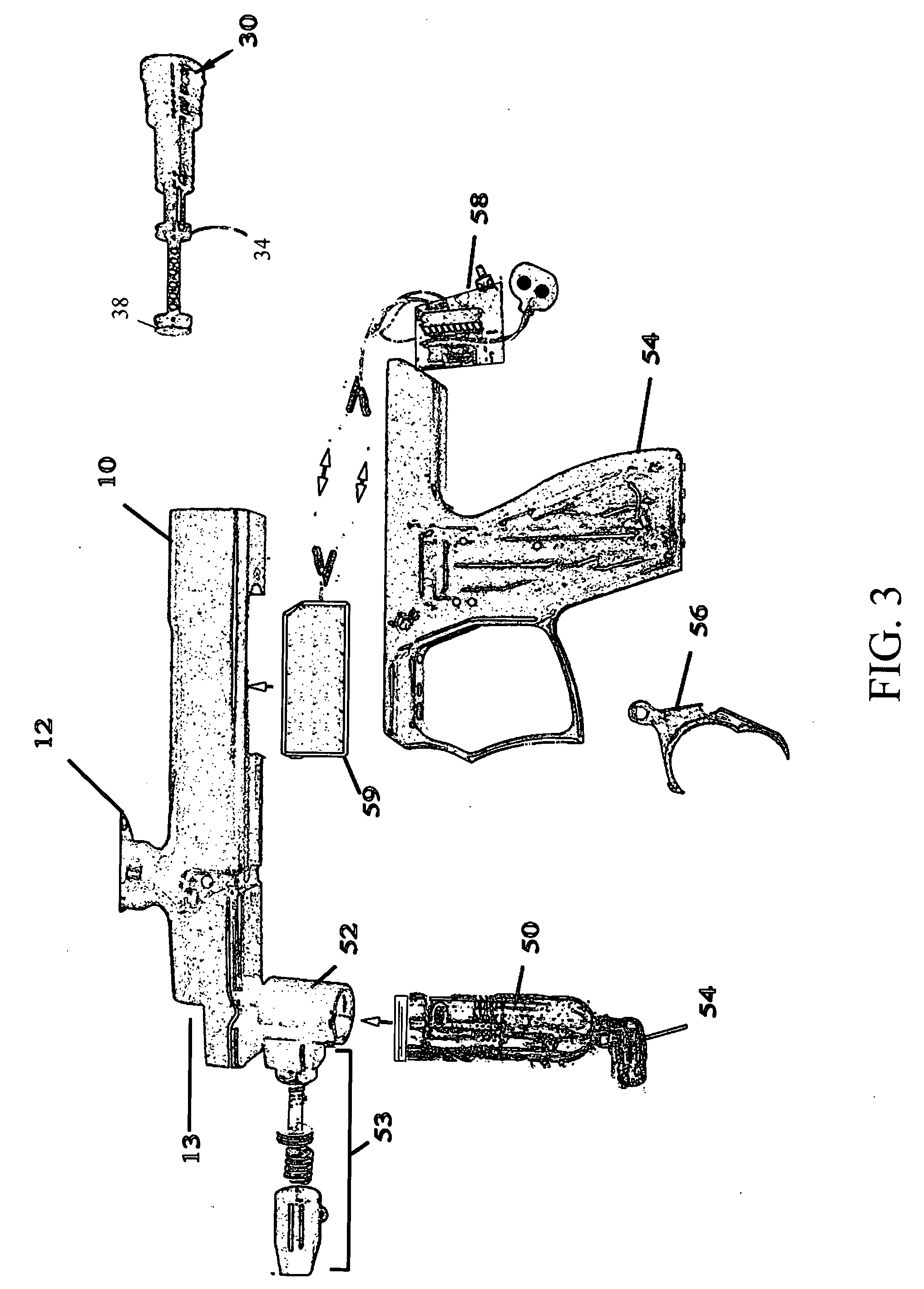
[0023]FIG. 1 is a perspective view of the paintball marker according to the present invention. The paintball marker includes a main body 10 with a detachable handle grip 54 and pivoting trigger 56. The main body 10 includes a muzzle 13 by which a paint ball is discharged through an extending barrel assembly 90, and a regulated gas inlet 52 for introduction of compressed gas into main body 10. Internally, the compressed gas is used to accomplish two things: 1) provide high-pressure gas charge (approx. 300 psi) to expel the paintballs, and 2) provide a low pressure gas charge (approx. 90 psi) for manipulating a firing mechanism. As will be described the unique electronic firing mechanism of the...


PUM


Abstract

An improved pneumatic firing mechanism for a paintball gun of the electronic (automatic) type, having selectable burst-firing modes and integrated bolt and ram to improve efficiency and yet simplify manufacturing. The firing mechanism generally comprises a bolt formed with a forward portion and a fixed portion, and a coaxial valve piston inside the bolt, the valve piston being formed with a central passage for directing compressed gas from the gas inlet of said main body into the compressed gas storage area, said valve piston selectively preventing the release of compressed gas from the compressed gas storage area. Low pressure is employed in the gun in order to move the bolt rapidly forwardly towards its front shooting position, where the bolt causes high pressure gas to be released into the barrel through a high pressure gas passageway running through the center of the bolt. The number of paintballs fired in a single burst can be set by the user.

Description

CROSS-REFERENCE TO RELATED APPLICATIONS[0001]The present application derives priority from provisional patent application No. 60 / 732,823 filed Nov. 2, 2005.BACKGROUND OF THE INVENTION[0002](1) Field of the Invention[0003]The present invention relates to paintball guns and, more particularly, to a pneumatic firing mechanism with selectable burst-firing modes and integrated bolt and ram.[0004](2) Description of the Background[0005]Paintball has become an extremely popular hobby and, for some, a profession. The guns used to fire the paintballs are referred to as “markers”. Paintball markers are pneumatic projectile launchers that fire encapsulated paintballs by releasing a burst of gas (typically CO2 or compressed air).[0006]Current paintball markers are very sophisticated devices comprising a reservoir of compressed gas connected to a regulator, and a trigger mechanism for actuating the regulator to discharge the gas, ejecting paintballs from the chamber through a barrel at between 28...

Claims


Application Information

Patent Timeline
IPC IPC(8): F41B11/32
CPCF41B11/64F41B11/62
Inventor COLE, CHRISTOPHER
Owner COLE CHRISTOPHER
Learn More