[0012] Downstream of the oil mist separation element, i.e. downstream in the direction of the gas flow, there is a pressure
regulator valve which has a bias that opens the pressure
regulator valve above a specified pressure in the line, in particular the pressure in the line between the oil mist separation element and the pressure regulator valve. In this manner, there is a biased valve which is fully open under normal operating conditions. A bias of this type can be achieved, for example, by realizing the valve in the form of a membrane-regulated valve. The membrane can then be located between the line and a
constant pressure such as
atmospheric pressure, for example. If the
pressure difference between the line and this pressure decreases, the membrane exerts increased pressure on a valve body which increasingly closes the valve. By means of this pressure regulator valve it is possible to protect the inlet side of the line, such as a
crankcase for example, against an excessive vacuum from an intake tract of an engine located on an outlet side of the line.
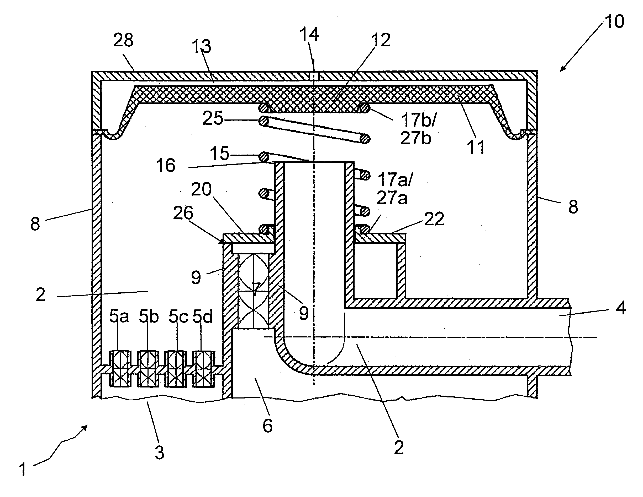
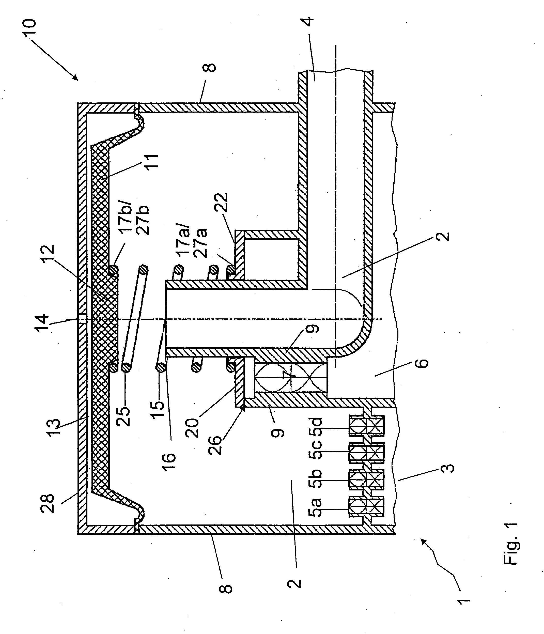
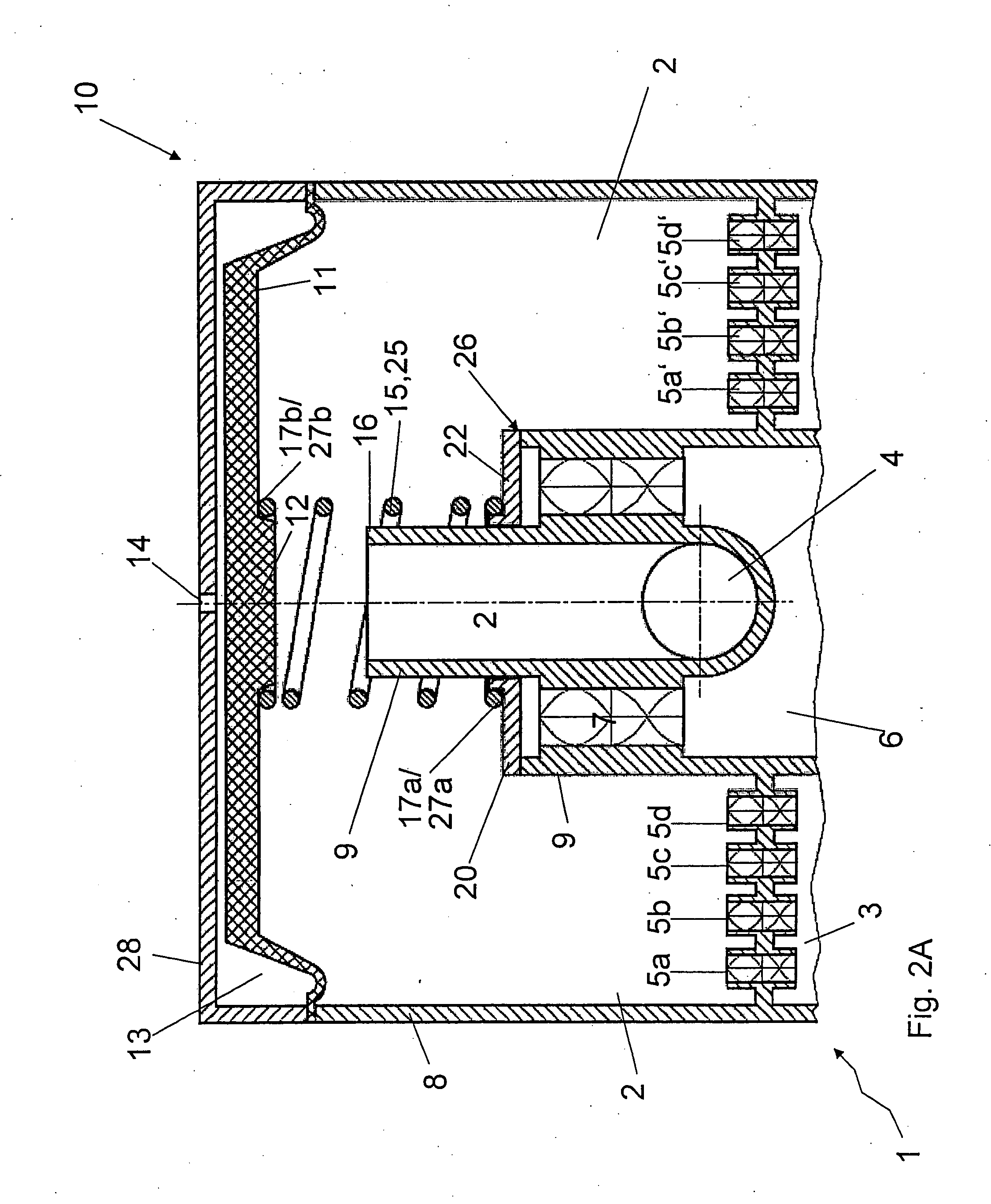
[0015] A decisive factor in this invention is that the pressure regulator valve and the bypass valve are functionally coupled or connected to each other. When the pressure regulator valve closes, it thereby increases the bias of the bypass valve. Therefore if the pressure regulator valve is closed, which normally occurs at a very high intake vacuum of the intake tract, the bias of the bypass valve is simultaneously increased. Under operating conditions of this type, the high vacuum of the intake tract is sufficient to empty the crankcase of the blow-by via the oil mist separation elements in the ventilation line, even if the blow-by flow is very large or the oil mist separation element, because of partial clogging, produces a large pressure drop. Therefore a bypass valve is provided that opens later at a high suction pressure to effectively clean the blow-by flow under these conditions, too, before uncleaned gas is transported through the bypass valve and the bypass line into the intake tract.
[0016] One particularly advantageous embodiment of this invention uses a membrane-regulated valve as the pressure regulator valve, in which the membrane is pulled toward the
valve seat, and a valve body is thereby moved toward the
valve seat to make the flow gap in the valve smaller if the suction vacuum is too high. Thus the resistance in the valve, i.e. the pressure drop, is increased and it becomes possible to reliably prevent the crankcase from being totally evacuated. At low suction vacuums, the membrane is in contact against the cap of the pressure regulator valve and opens the valve all the way.
[0018] Also provided is a bypass valve in which a valve body is pressed by a spring onto the aperture of the bypass valve. The bias of the spring consequently determines the force and thus the pressure difference necessary to lift the valve body of the bypass valve out of its seat and thus to open the bypass valve. In one particularly advantageous variant, the bypass valve can be located immediately next to the pressure regulator valve. In this manner, when there is a
high pressure difference in the intake tract, the pressure regulator valve is increasingly closed and simultaneously the bias of the bypass valve is increased. When the vacuum in the intake tract is high, the ventilation of the crankcase is guaranteed even in the event of a high blow-by flow or a partial clogging of the oil mist separator element.
[0020] In an additional advantageous variant, at least one separation element is also integrated into the bypass. In this manner, an oil mist separation also occurs in the blow-by gases transported through the bypass. In this manner, completely uncleaned blow-by gas is prevented from getting into the intake tract. An arrangement of this type could also be called an adaptive oil mist separator, because different oil mist separation paths are opened as a function of the blow-by amount and the pressure conditions in the intake tract.
[0021] The oil mist separator claimed by the invention has a better control characteristic and a higher degree of separation than unregulated oil mist separators. The protection of the oil separator against failure is also improved. Because the valves (pressure regulator valve and bypass valve) are next to each other, the number of replacement parts required in the oil mist separator claimed by the invention is reduced, which results in easier installation and cost advantages.

